Lab: Digital Input and Output with an Arduino
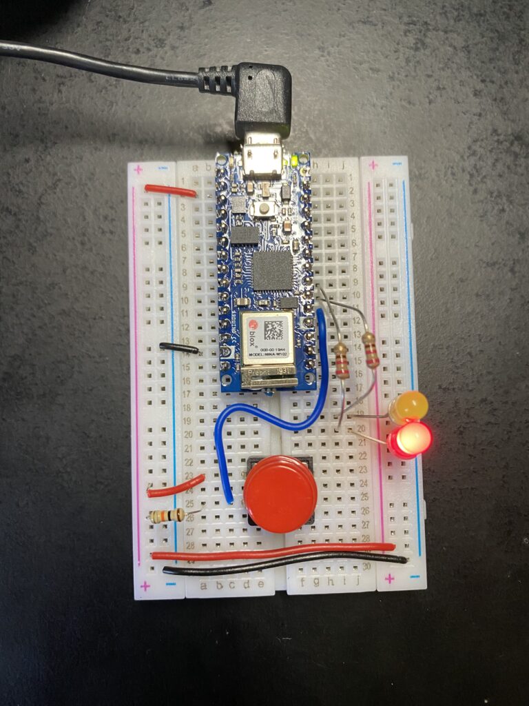
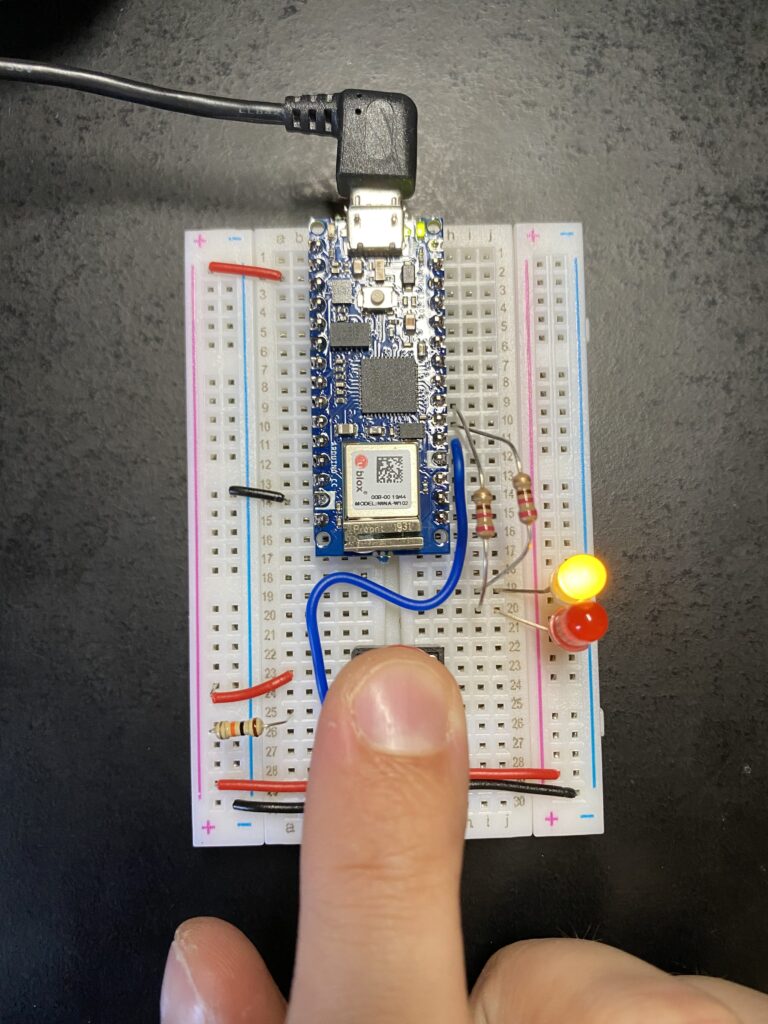
This week I went hands on with an Arduino Nano 33 IoT and setup circuits with logic running through the Arduino. For this first lab I made use of digital IO (inputs and outputs) which are capable of reading the values on and off. The idea for this lab was to control an LED turning on and off through programming. A switch connected to a digital IO pin is used to indicate when to trigger the LEDs. Here is the circuit and code:
void setup() {
  pinMode(2, INPUT);    // set the pushbutton pin to be an input
  pinMode(3, OUTPUT);   // set the yellow LED pin to be an output
  pinMode(4, OUTPUT);   // set the red LED pin to be an output
}

void loop() {
   // read the pushbutton input:
   if (digitalRead(2) == HIGH) {
     // if the pushbutton is closed:
     digitalWrite(3, HIGH);    // turn on the yellow LED
     digitalWrite(4, LOW);     // turn off the red LED
   }
   else {
     // if the switch is open:
     digitalWrite(3, LOW);     // turn off the yellow LED
     digitalWrite(4, HIGH);    // turn on the red LED
   }
 }
By default the red LED is on. When the button is pressed the digital input pin 2 reads a change in value and triggers the red LED (pin 4) to turn off and yellow LED (pin 3) to turn on.
The sample code for this worked as expected! On to the next lab…


