Lab: Switches and Pushbuttons
In this lab I reviewed different types of switches and their terminology. In addition to using switches in a few different breadboard circuits I also created a switch of my own!
For my first circuit I created my own switch. Looking at what I had on hand I decided to repurpose some cardboard packaging, copper tape, and a small neodymium magnet to create a switch that would be triggered by an object containing ferromagnetic metals.
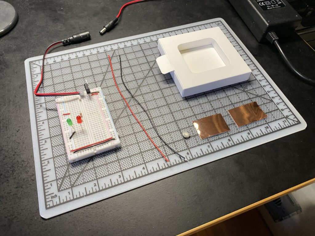
The materials I planned to use.
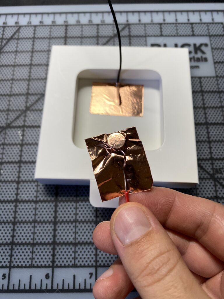
To keep things simple I decided to take advantage of the adhesive in the copper tape to hold things together. My thought was that the switch could hang on the underside of the box and that the weight of the magnet would naturally open the switch. Then in the presence of ferromagnetic metals above the magnet would be lifted and close the circuit.

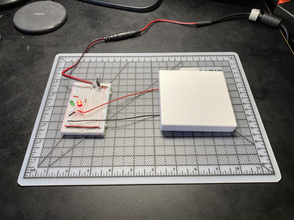
The LEDs I would have liked to wired for only one to come on at a time, perhaps red to indicate that the circuit was on, then green when the switch was triggered. I wasn’t sure how to do this with my parts on hand however and instead wired the red LED to remain on and the green LED in parallel running through the switch. Here is the final setup.
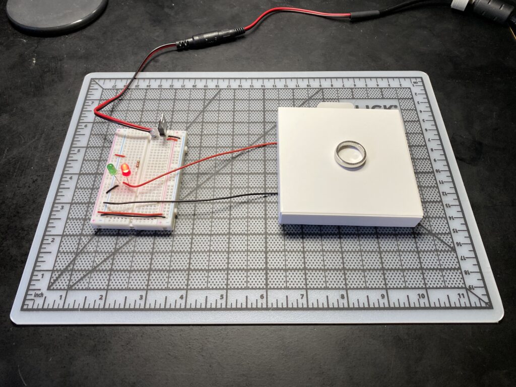
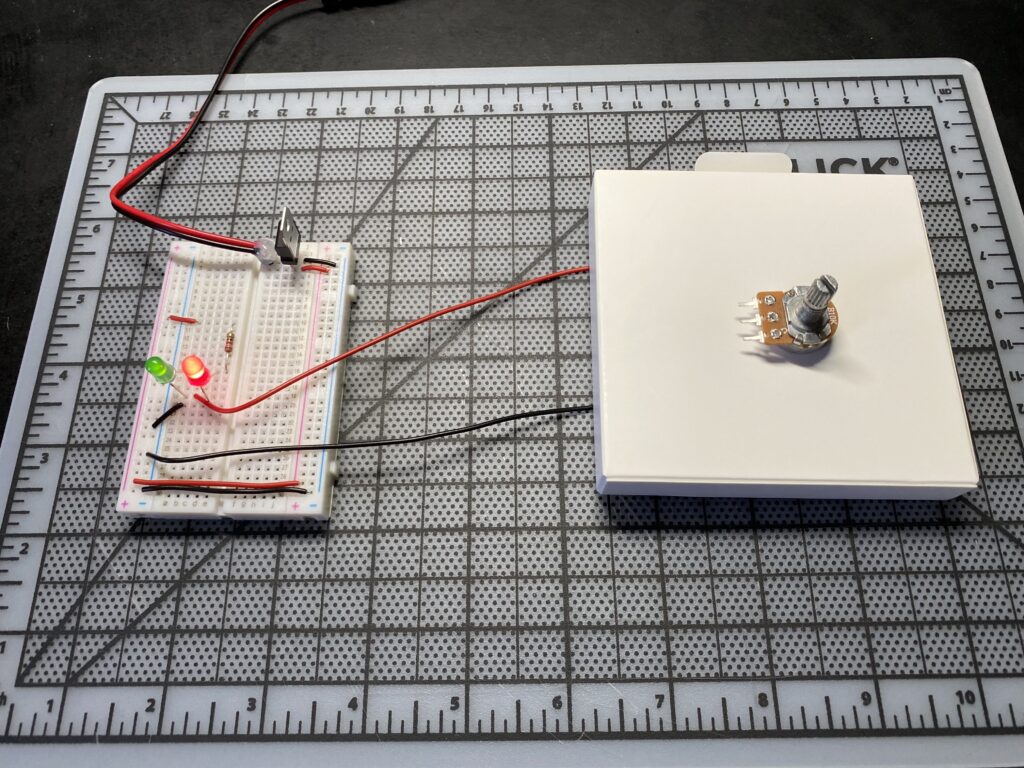
From my test my metal ring did not trigger the switch, and therefore must not be ferromagnetic metal which I know to be true because it is cobalt chrome. The potentiometer did trigger the switch and therefore must contain ferromagnetic metals.
I was expecting for the green LED to be brighter. Reflecting now I suspect there must have been resistance in my DIY switch to cause this.
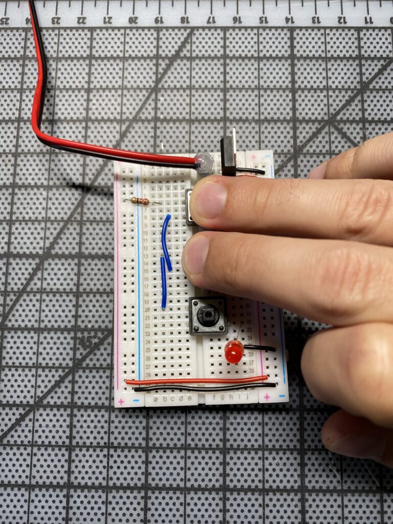
Next I created a couple of circuits on the breadboard first in parallel then in series.
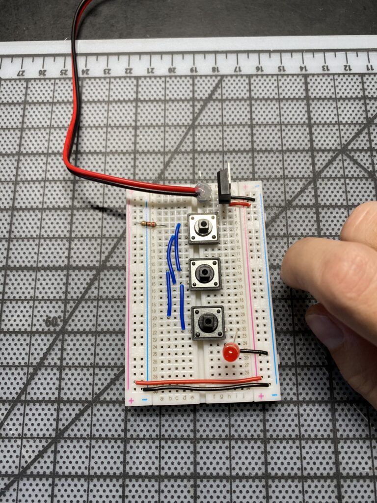
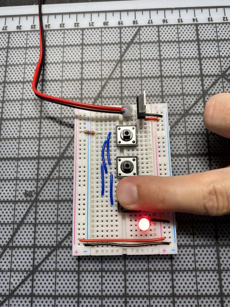
The parallel switches allowed any one of the switches to power the LED.
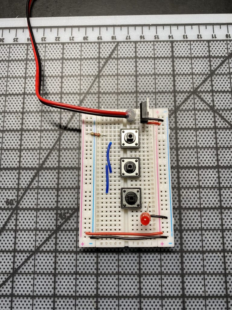
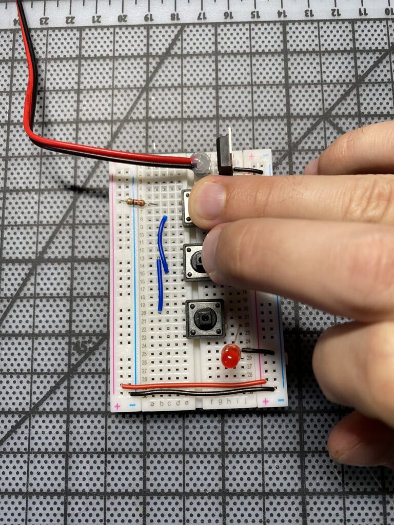
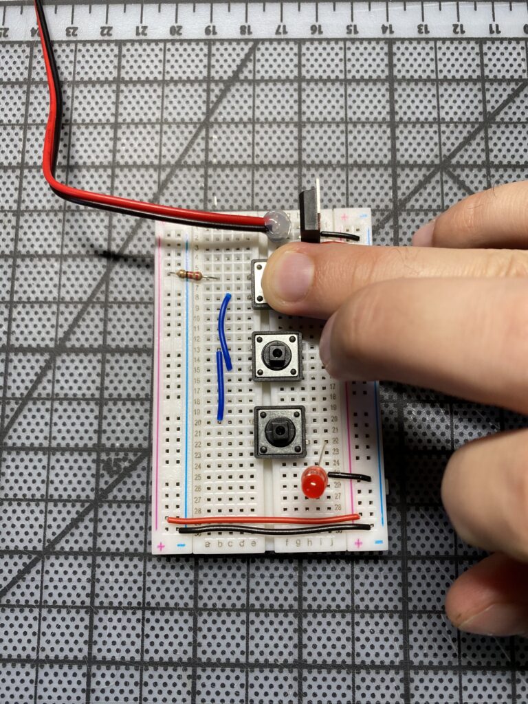
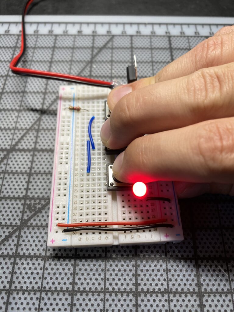
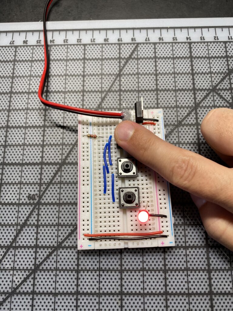
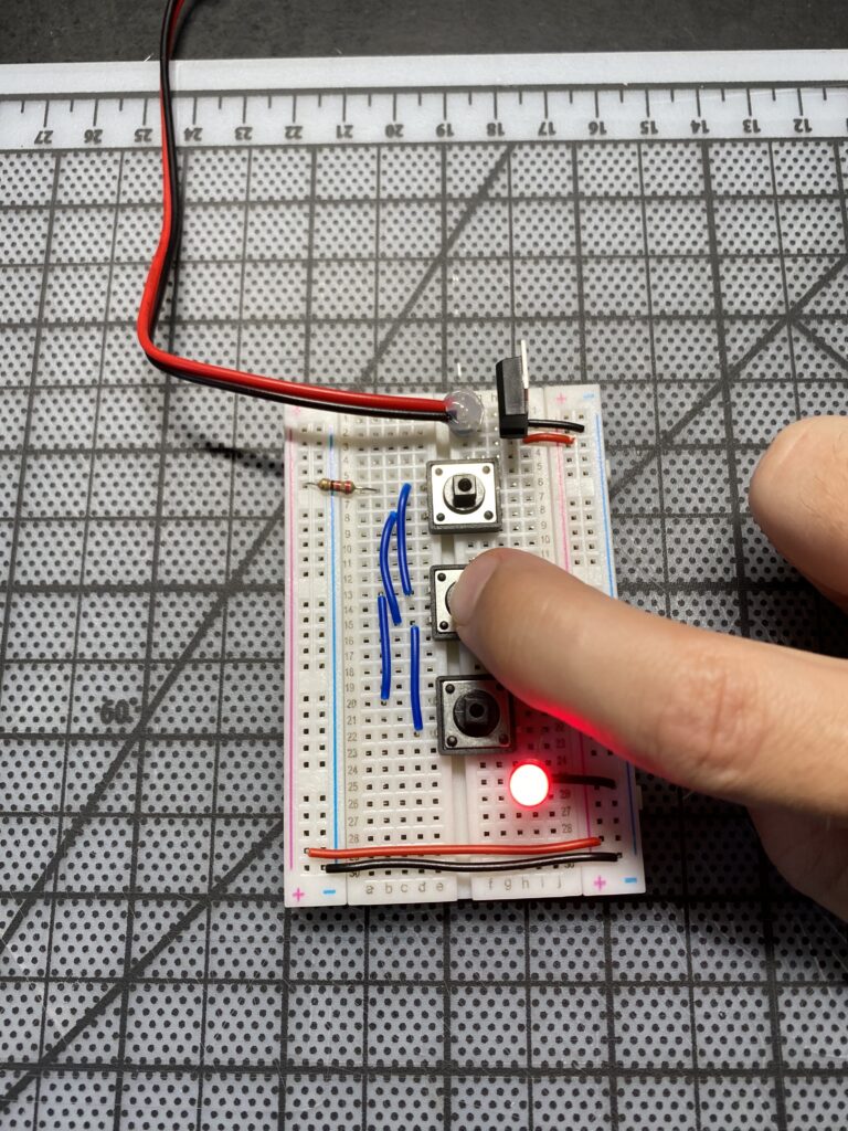
The switches wired in series was much easier to wire but required each switch to be closed for the LED to light. Good to know!
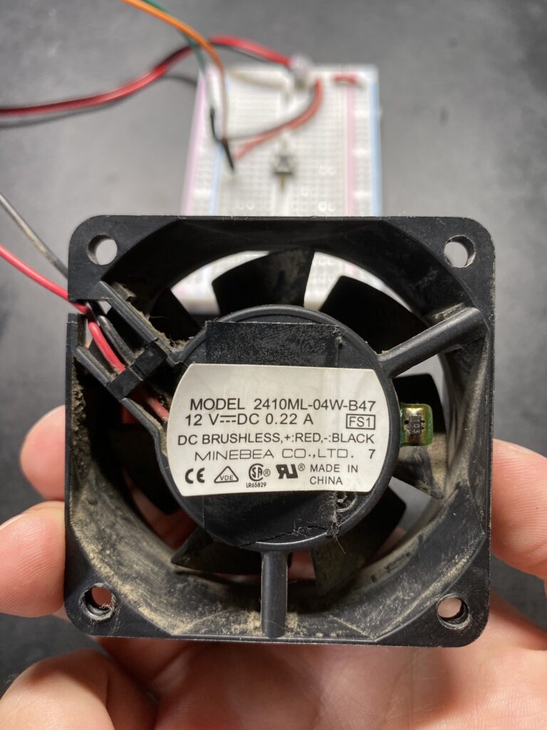
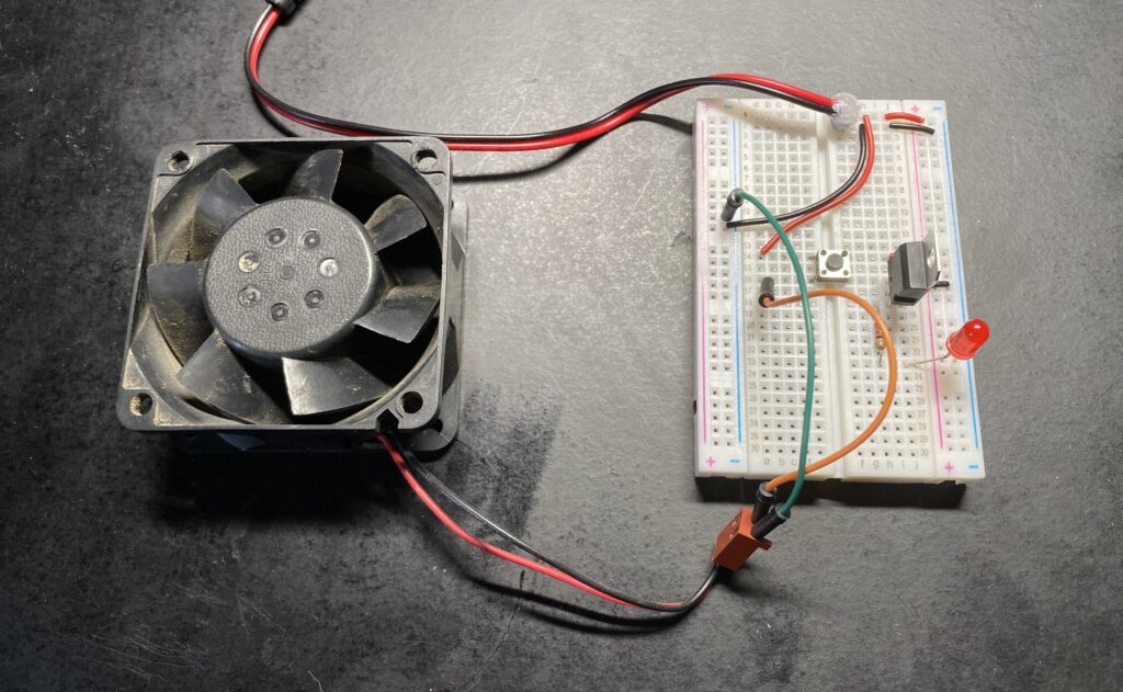
Next I wired up a motor. Conveniently I had a 12 volt fan on hand from an old PowerMac G4 tower. My 12 volt power supply was perfect for this.
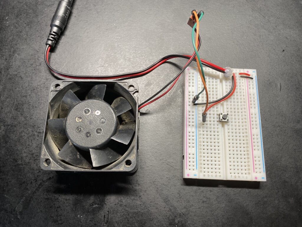
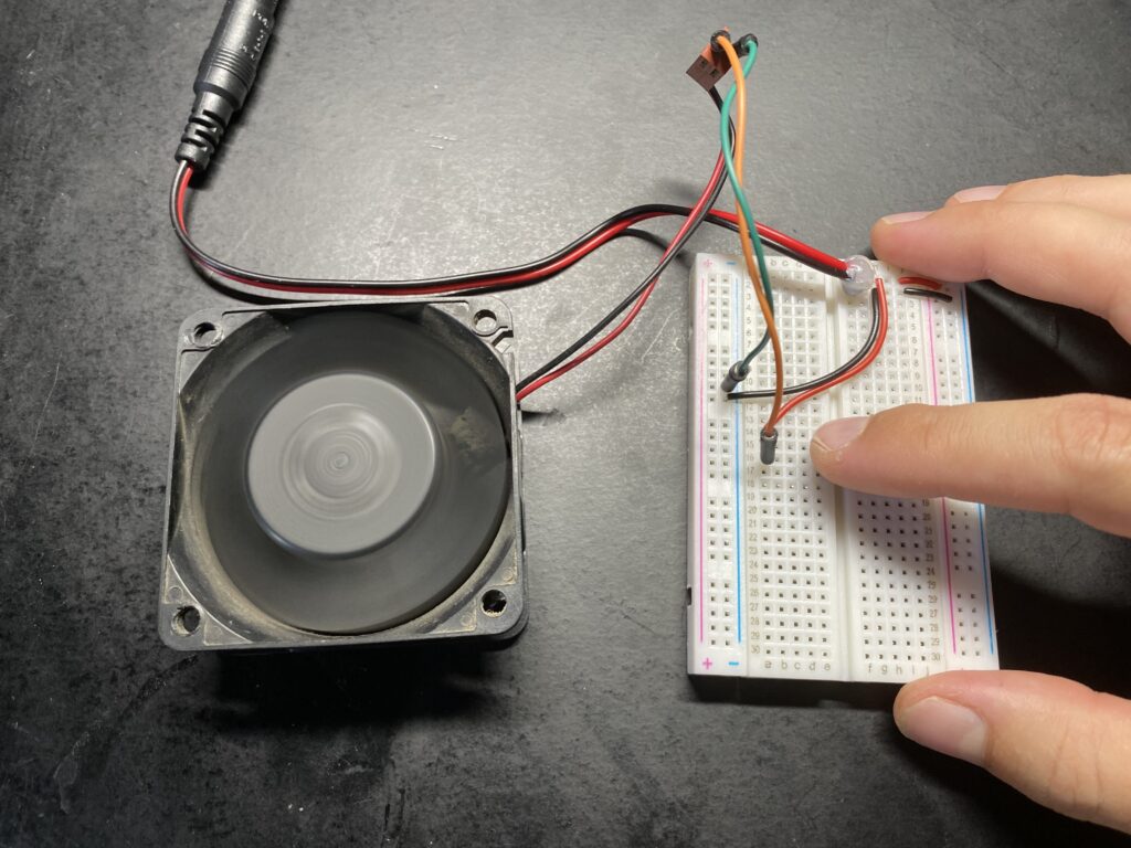
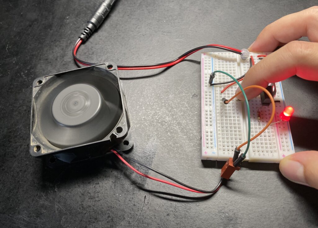
Next I added an LED to the circuit. I quickly discovered that my pushbutton switch was not dual pole so I would need to get more creative about the circuit construction to supply 12 volts to the motor and 5 volts to the LED. I ultimately achieved this by moving the power regulator in series after the switch just for the LED.
That’s all for now!


