Lab: Electronics
In this lab I reviewed the basic functions of a multi-meter then created a few circuits using LEDs, resistors, buttons and a potentiometer.
Making my way through the settings on the multimeter I started with the diode continuity function.
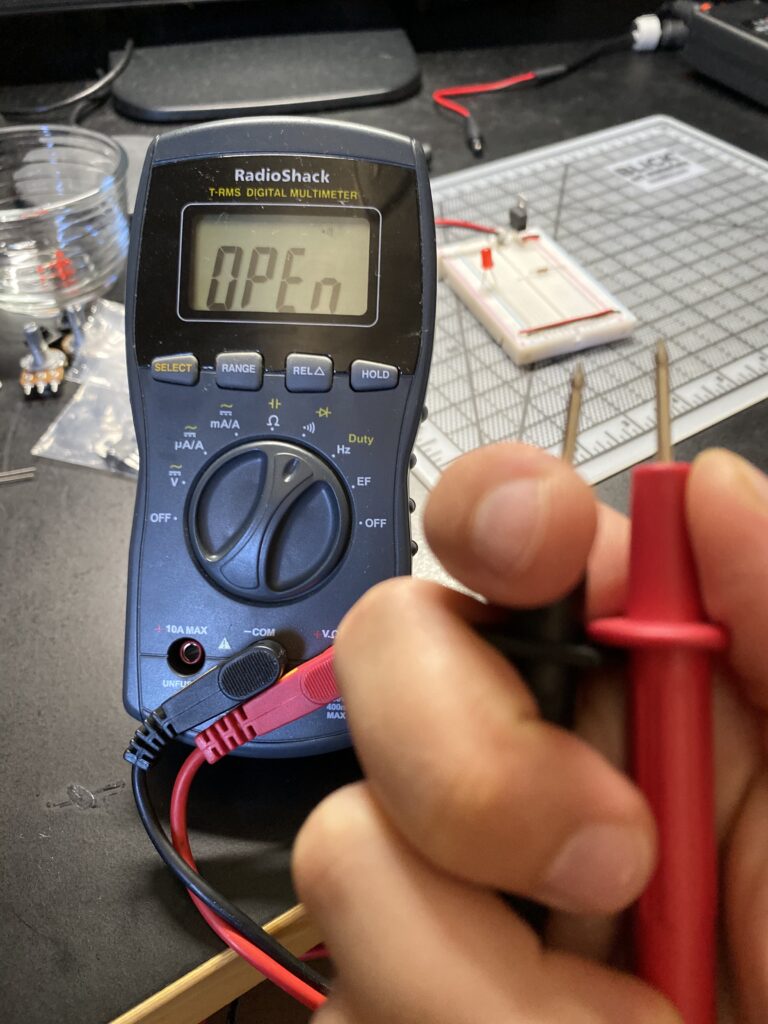
Keeping the multimeter probes apart in the continuity function results in an “Open” reading. 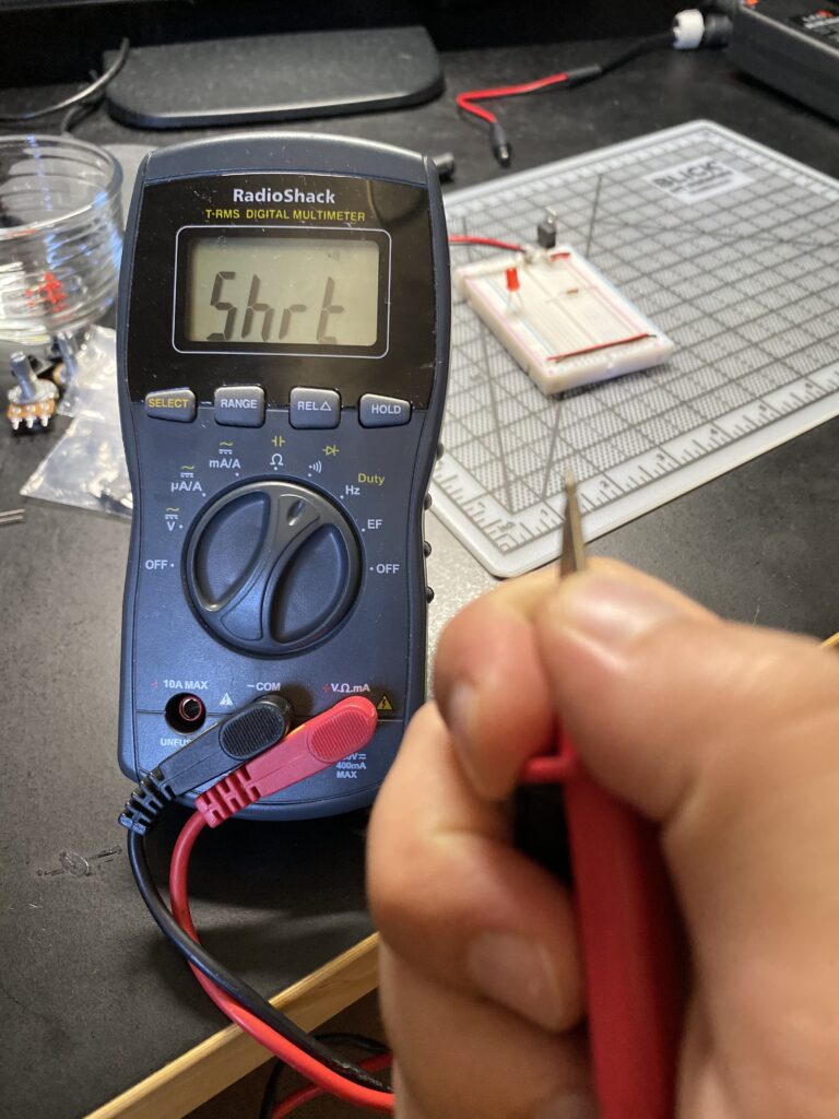
Touching the probes in the meter continuity function results in a loud beep and “Shrt” readout on the screen.
Holding the multimeter probes apart my multimeter read “OPEn” indicating that the circuit is open and there is no flow of electrons. Touching the probes together the screen read “Shrt” for short, indicating a closed circuit where electrons flow with no resistance.
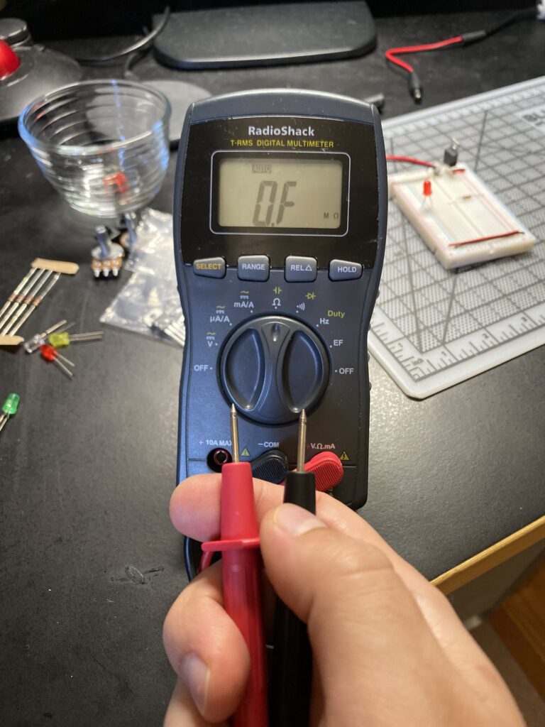
Switching to measure resistance with the multimeter without touching the probes results in a reading of 0 ohms. 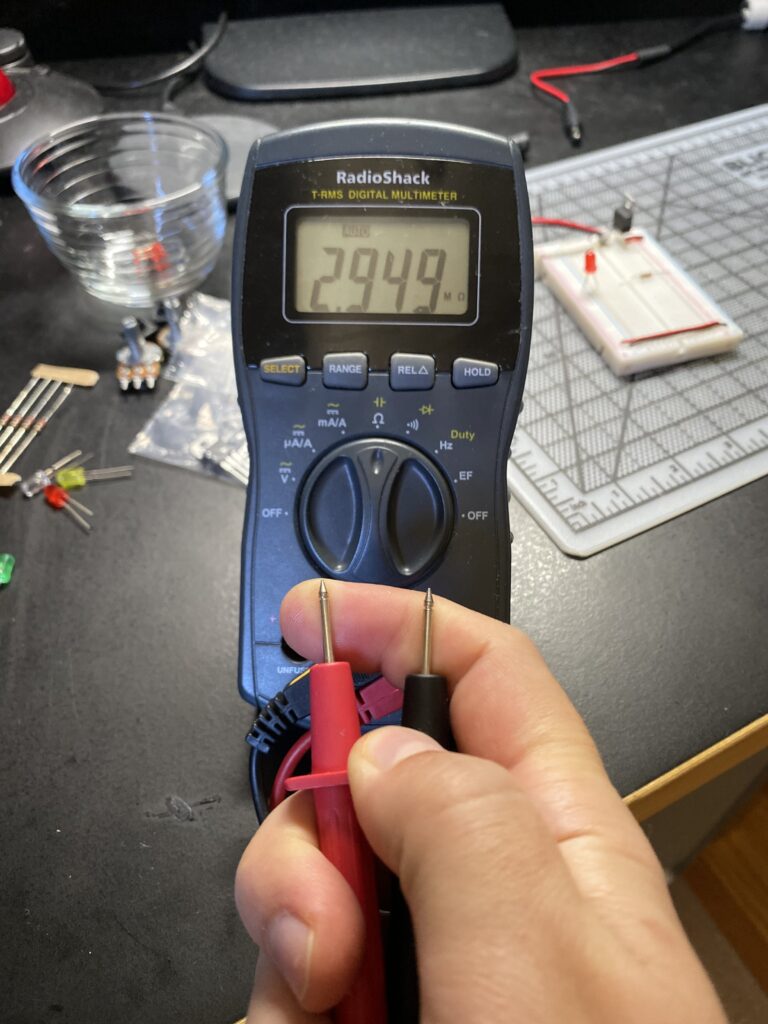
Measuring the resistance using the probes on the multimeter results in a reading of 2.949 milliohms.
Next I measured resistance with an open circuit, then using my finger as a conductor. My multimeter is auto ranging so it automatically scales the reading to the nearest whole unit. In the case of my skin the resistance reading was 2.949 milliohms.
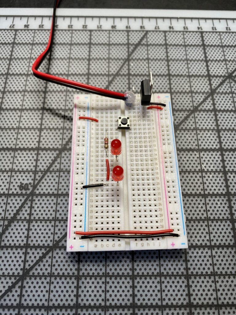
Next I setup a breadboard to take voltage readings at various points in the circuit.
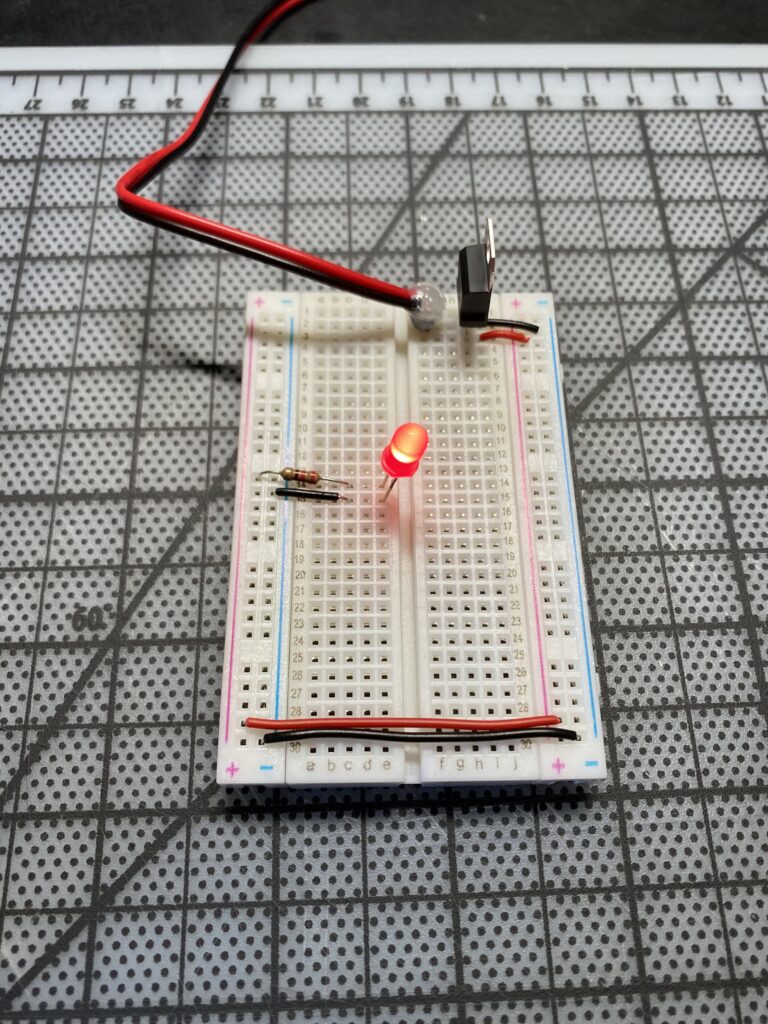
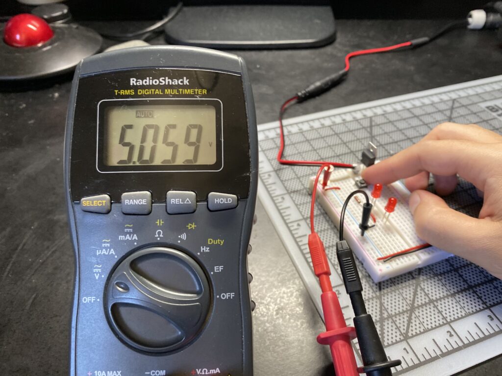
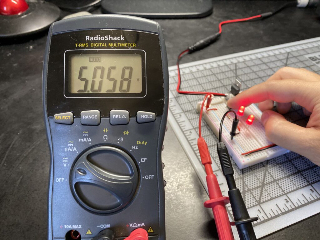
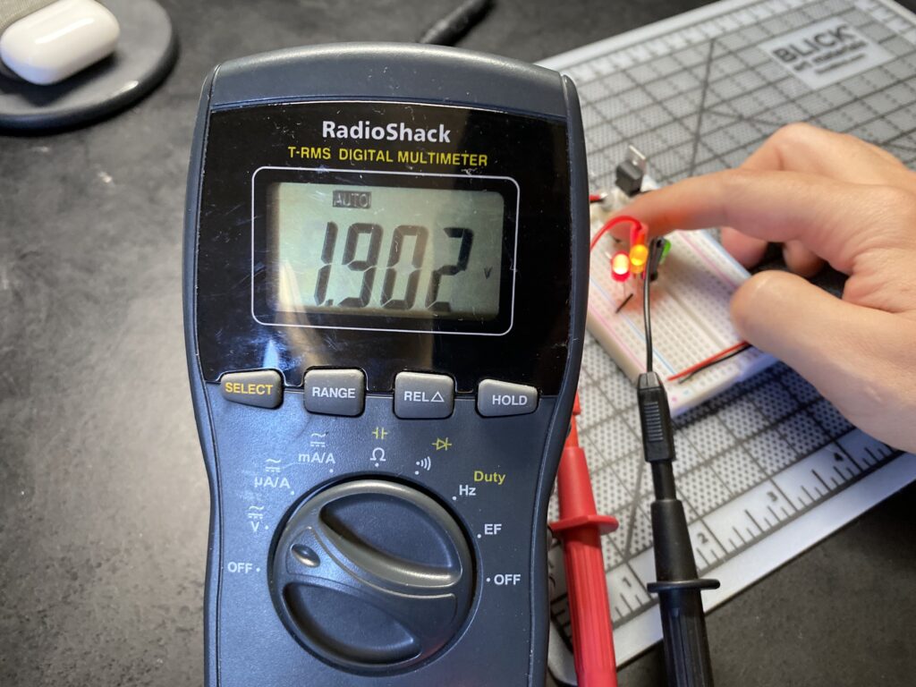
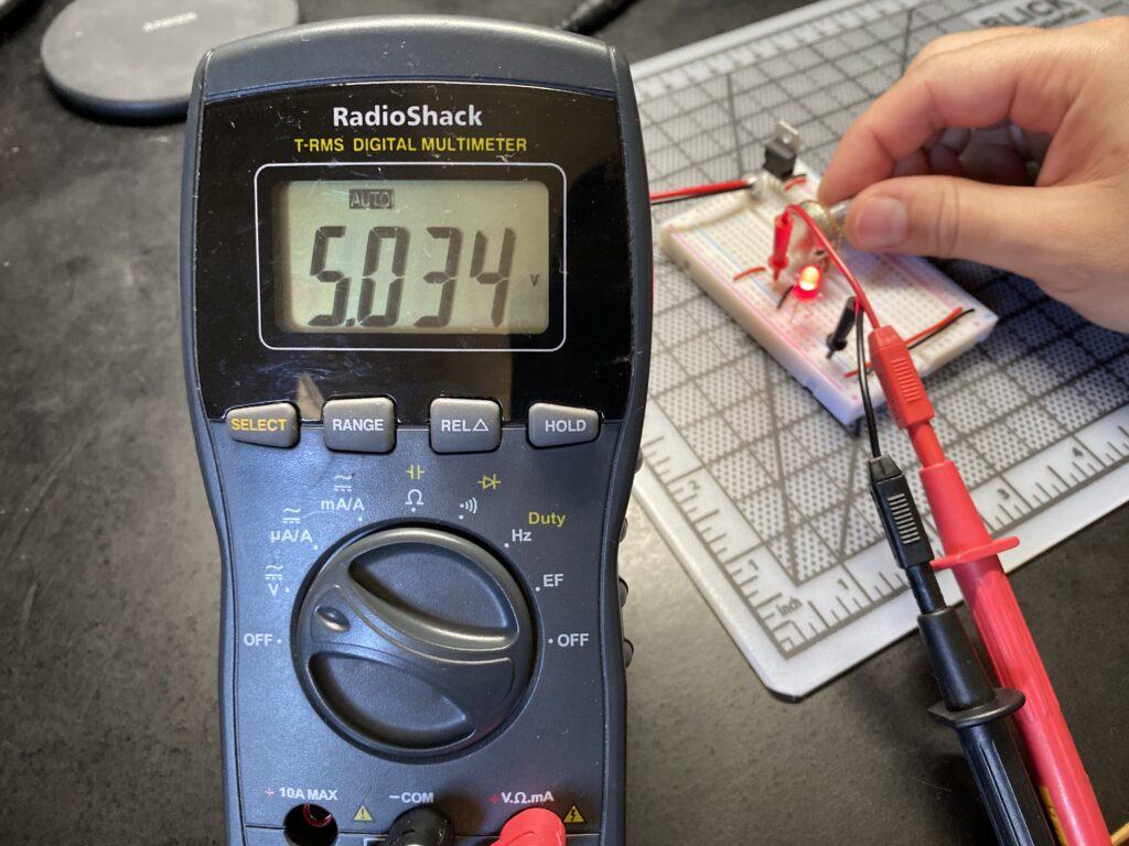
I have setup and powered a basic 5-volt circuit with a red LED and 220ohm resistor. 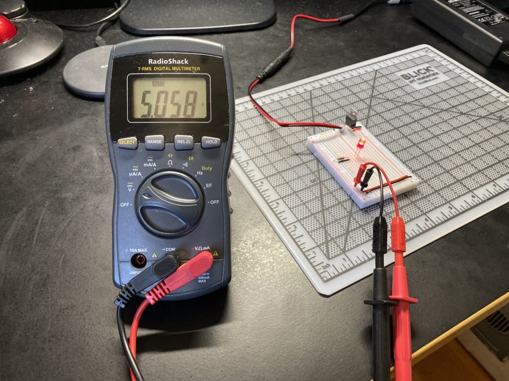
Checking the voltage of the circuit finds a reading of 5.058 volts. 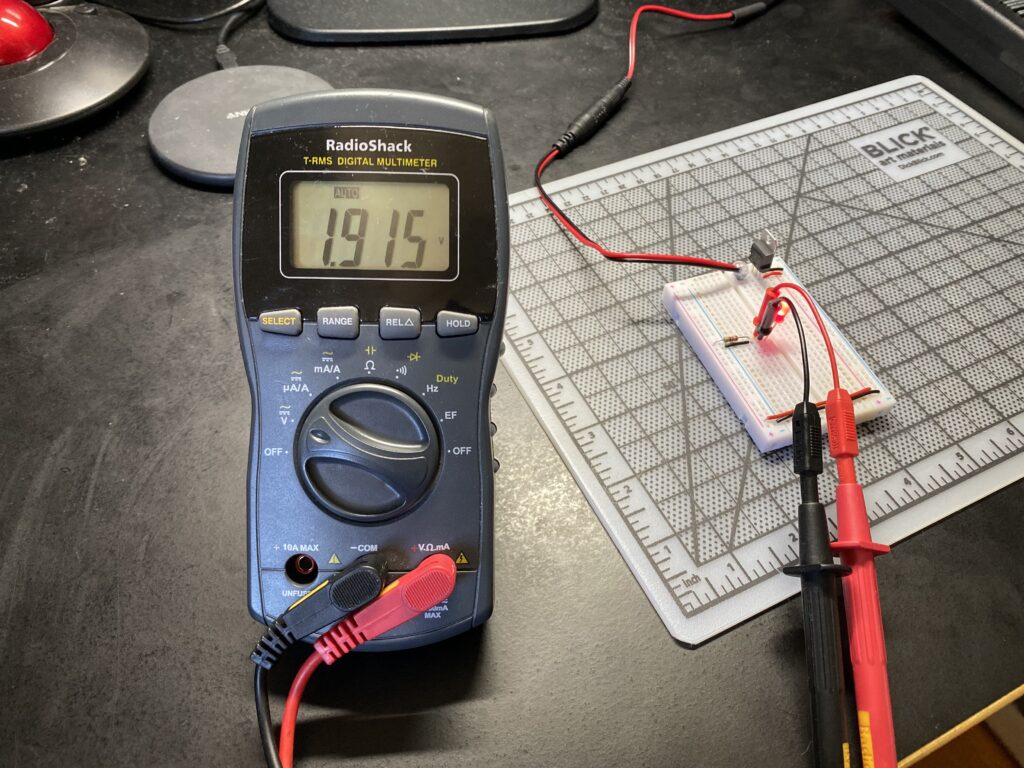
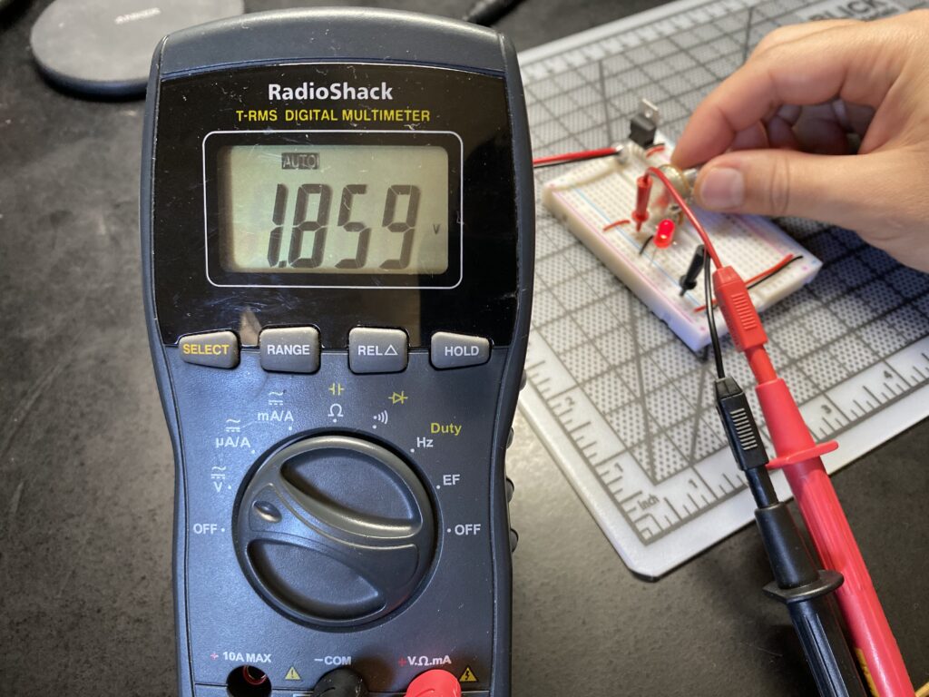
Probing the voltage drop across the red LED reads 1.915 volts.
The circuit voltage, due to the 7805 voltage regulator, is approximately 5 volts. Using the probes to measure the voltage drop across the red LED the reading is 1.915 volts. This “loss” of energy is accounted for by light and heat emitted from the LED.

Quick break with my dog Cooper.
Had to take a quick dog break! My dog Cooper was patiently waiting for a walk. He is a very good boy.
Ok, back from a walk and time to add a few more components to the board.
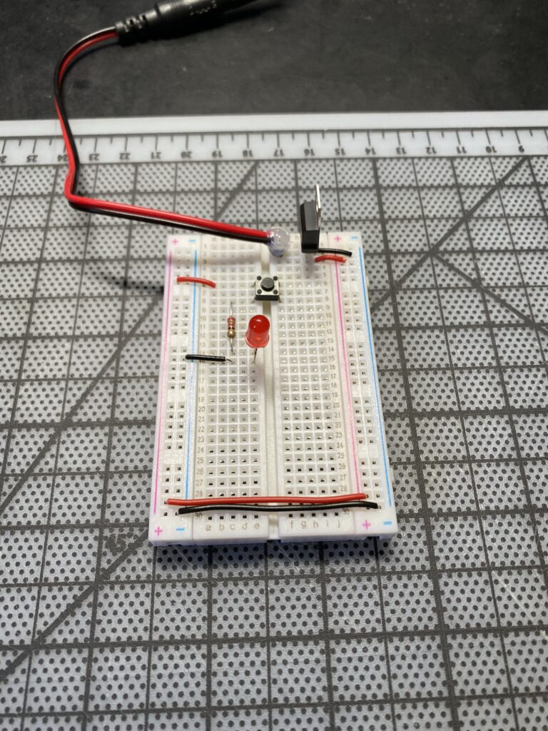
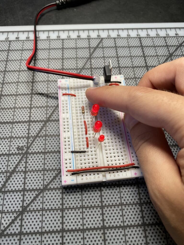
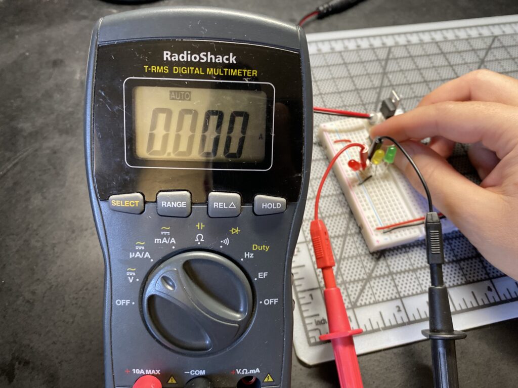
Adding a pushbutton switch to the circuit results in a naturally open or “off” position. 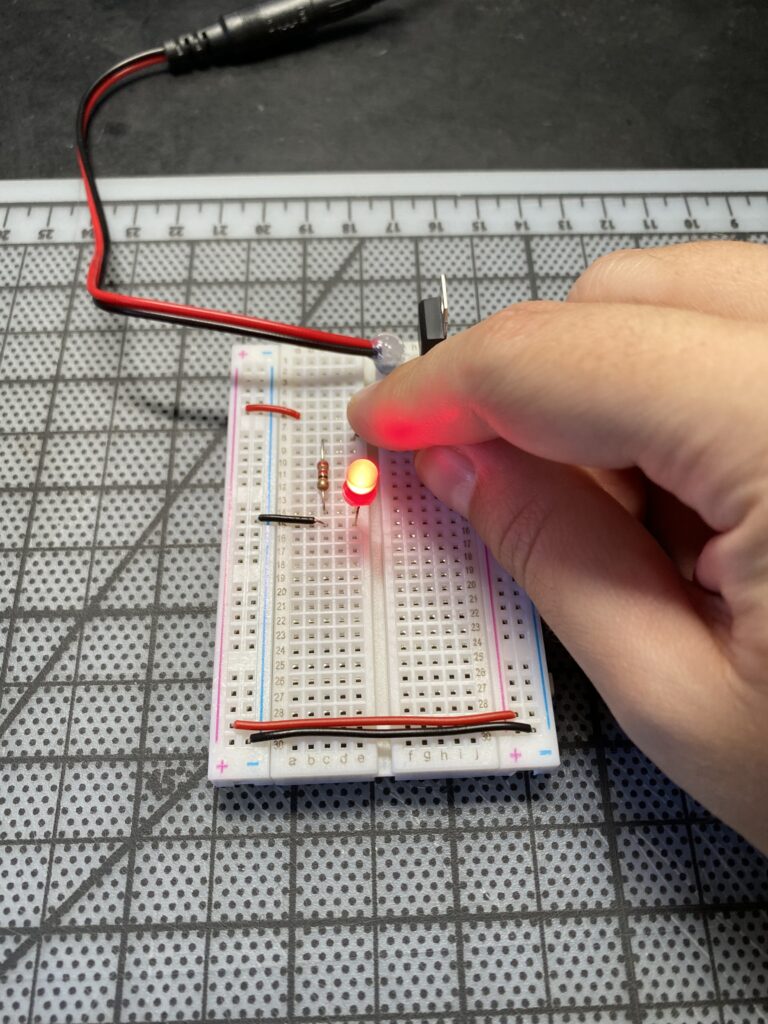
Pushing the button closes the circuit and turns on the red LED.
A pushbutton switch!
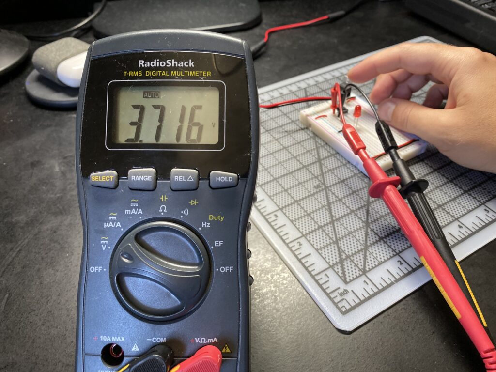
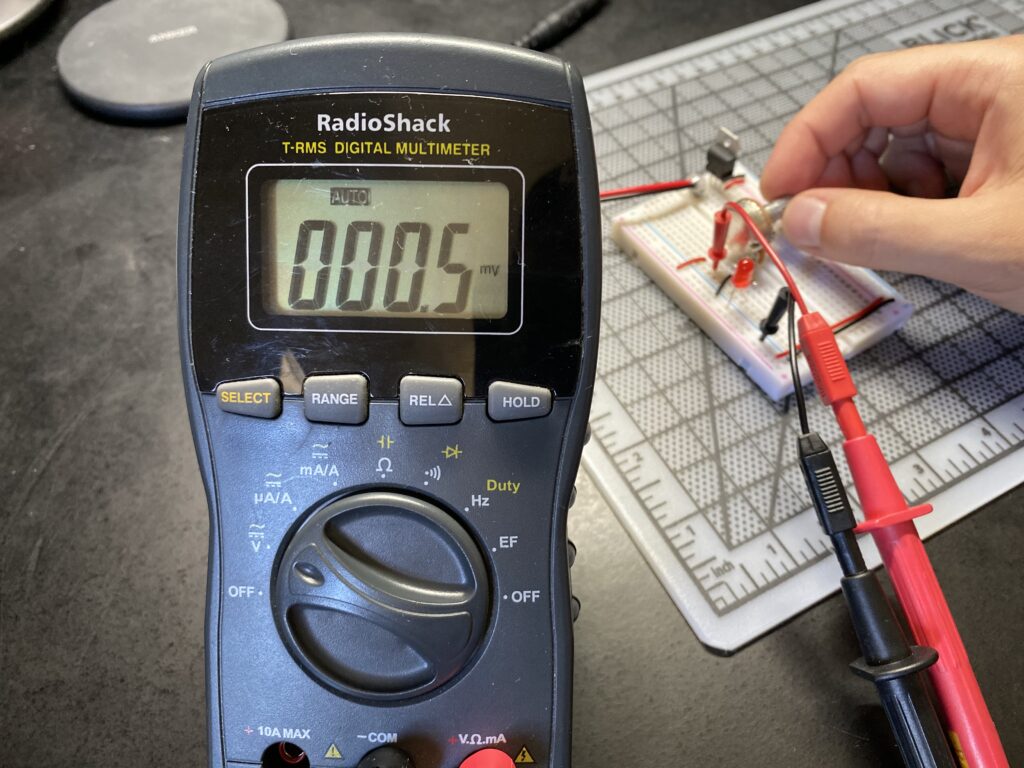
Reading the voltage across the pushbutton reads 3.716 volts 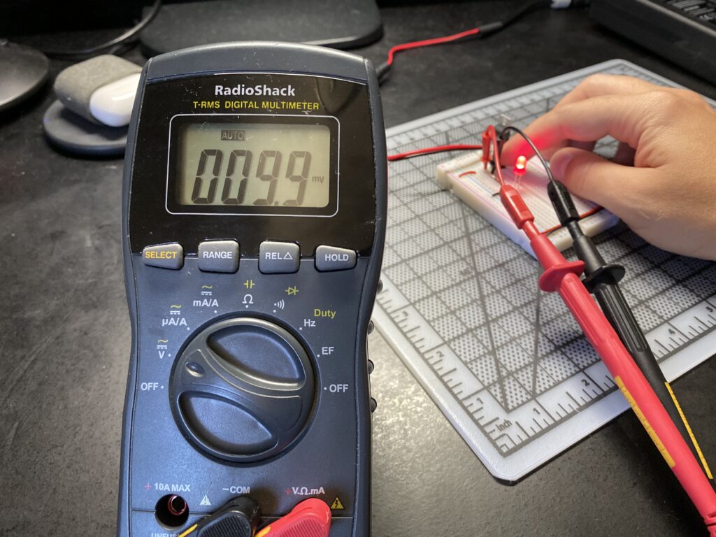
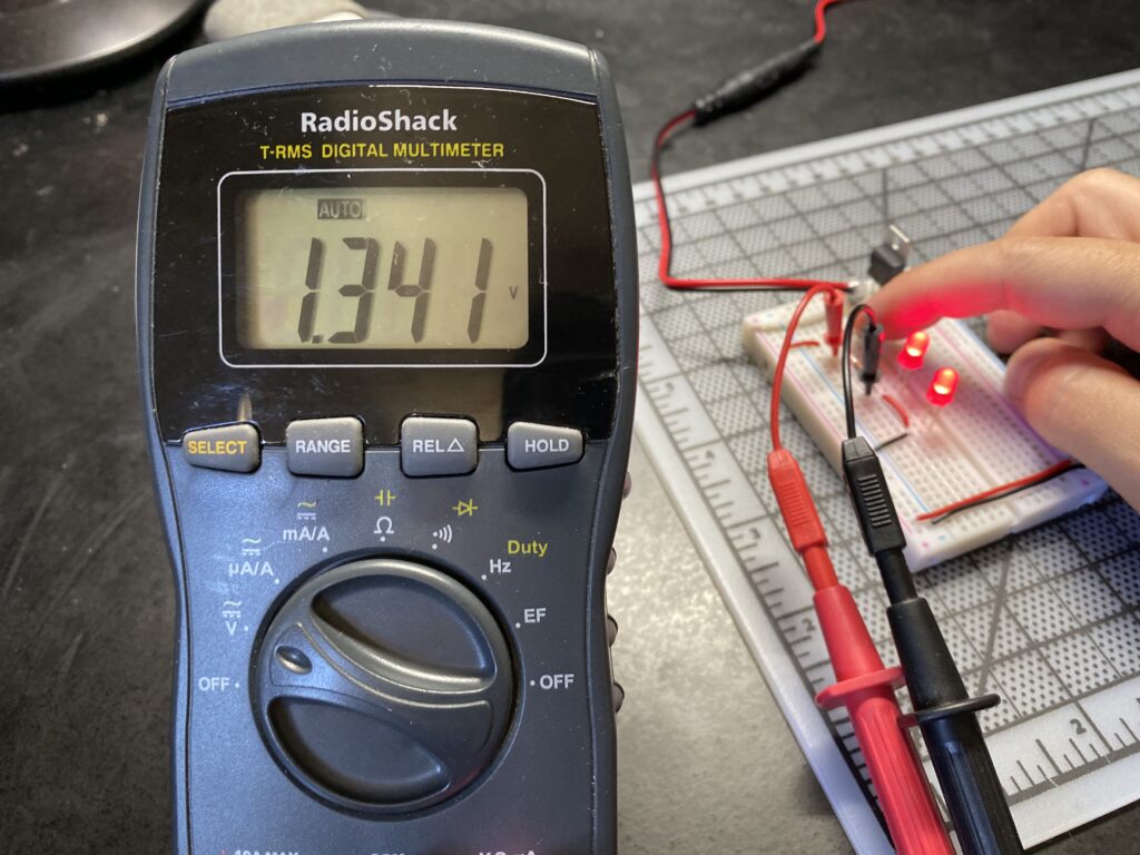
Pressing the button on the breadboard drops the voltage down to 9.9 millivolts. 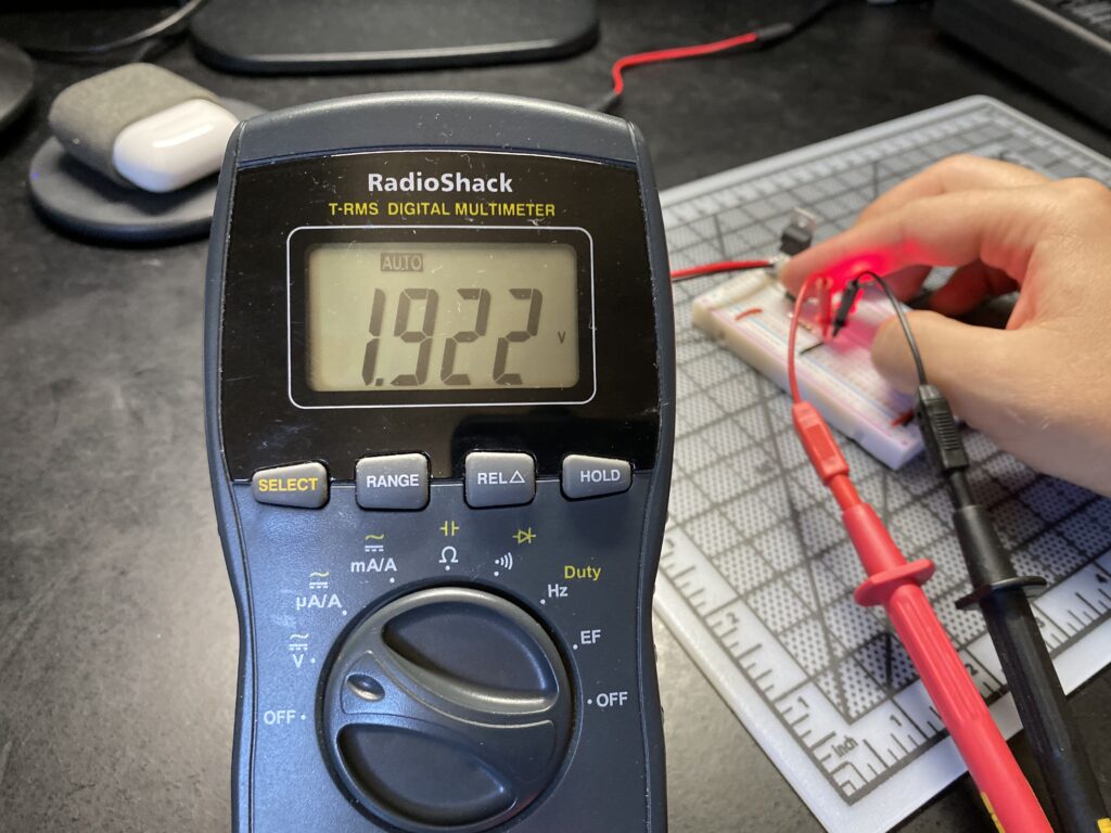
The voltage reading across the red LED is 1.922 volts. 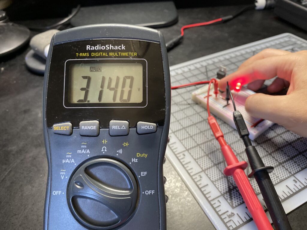
Reading the voltage drop across a few different components and points on the board I find that strangely there is a 9.9 millivolt voltage drop across the pushbutton switch. This will seem more relevant later…
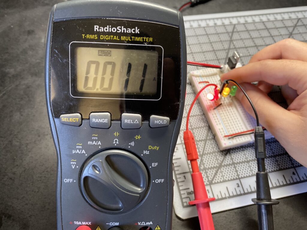
Next I expand the circuit to include an additional red LED in series.
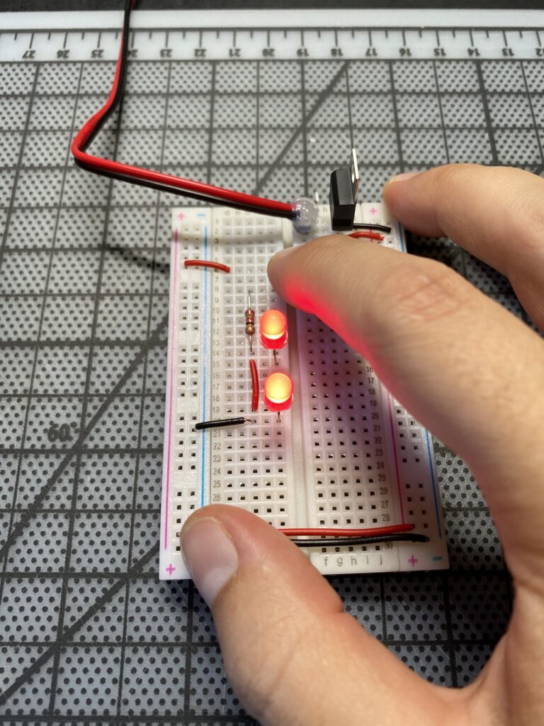
Pressing the pushbutton both LEDs turn on as expected.
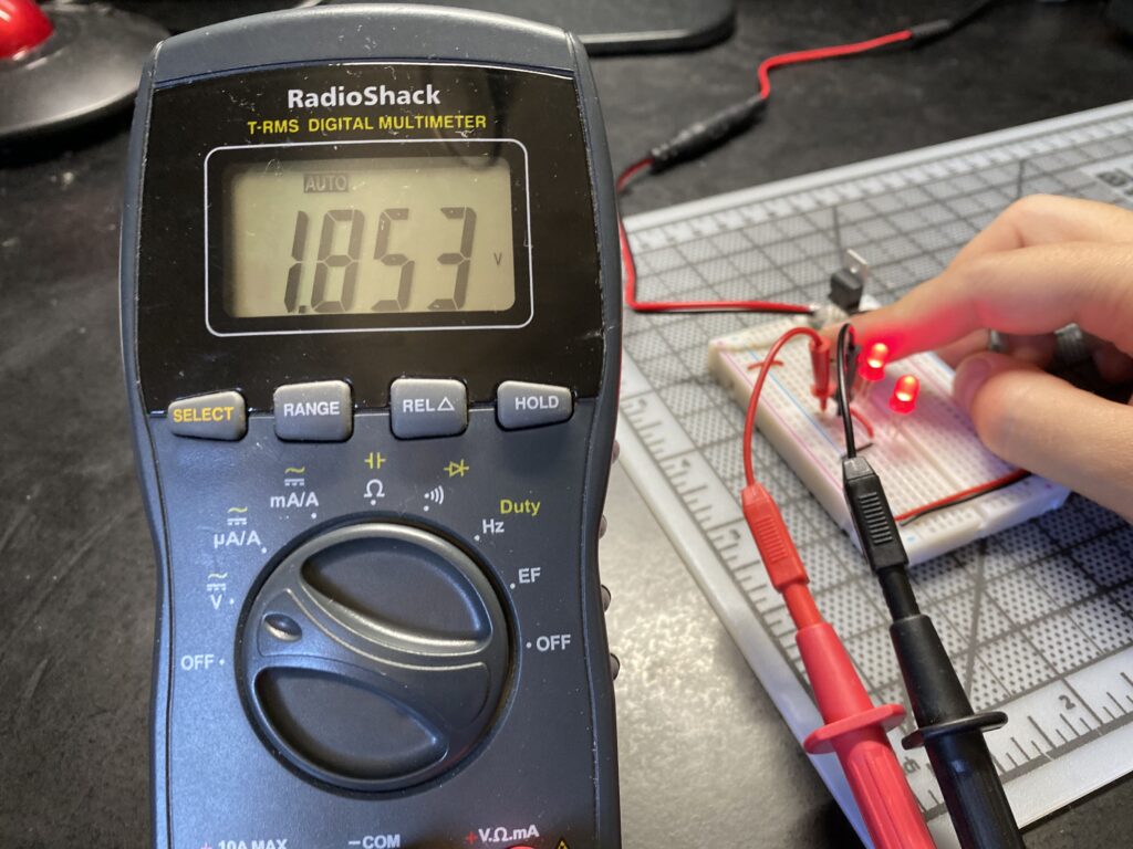
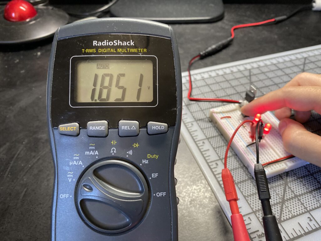
I continued to measure the voltage drop around the circuit. A drop of 1.3 volts across the resistor, 1.85 volts across each of the matching red LEDs, and the board total voltage of 5 volts. 1.3 + 1.85 + 1.85 = 5, all of the electrons are accounted for. Importantly the voltage drop for the two LEDs is now less than a single LED which was 1.9 volts. Looks like we’re running out of power.
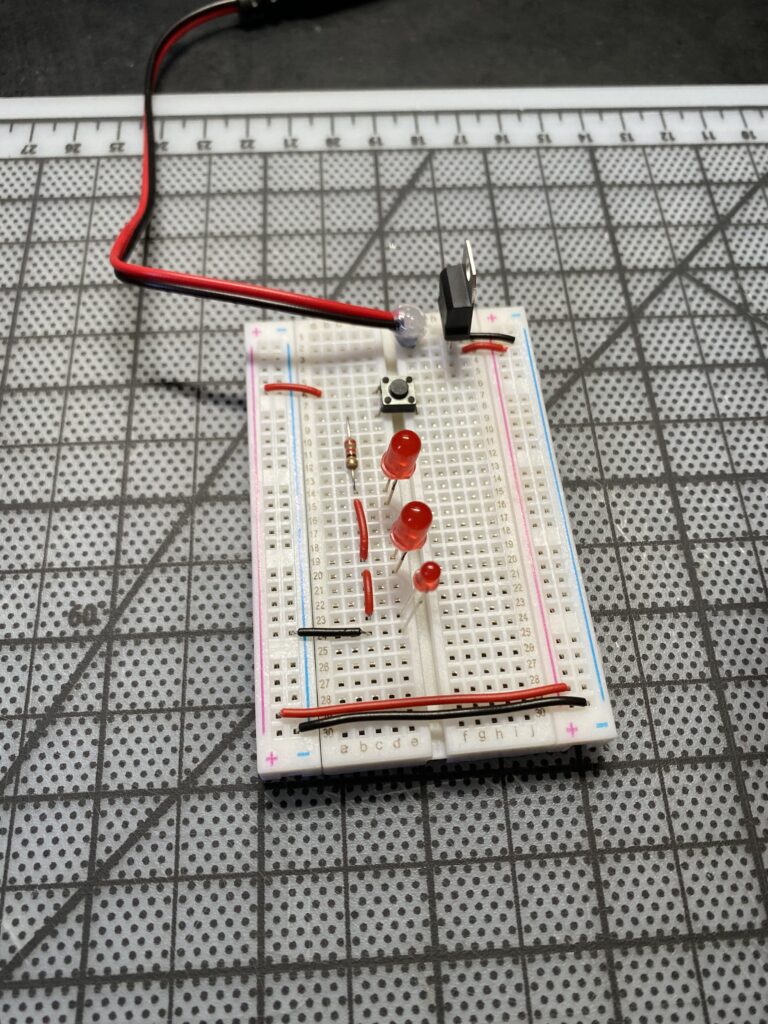
Adding a third smaller LED they were noticeably dimmer. The voltage drop of three LEDs is too much.
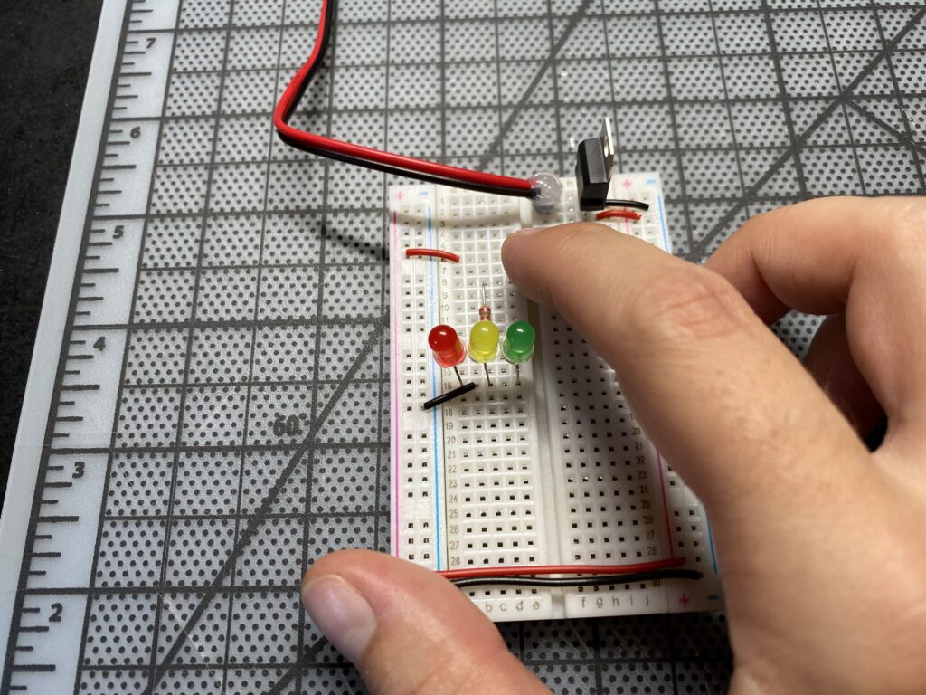
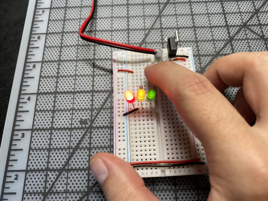
Next I rearranged the components and ran three LEDs in parallel. Interestingly they all light! This configuration is much better than running them all in series, which reminds me of the WS2812 LED strips I have used in the past that also supplies power in parallel.
Measuring the voltage drop across one of the LEDs the reading is 1.9 volts. Much healthier.
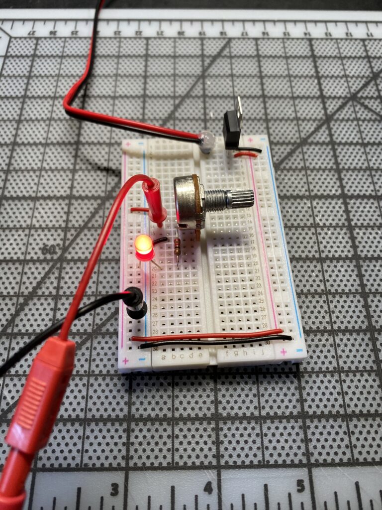
The breadboard is setup with probes at the beginning and end of the circuit.
Now for a different setup. Next I added a potentiometer in series with a single LED.
Measuring voltage between the beginning and end of the circuit results in the total 5 volts.
Turning the knob on the potentiometer varies its voltage drop, resulting in the red LED getting brighter or dimmer.
This lab has left me with some good thoughts around voltage drops. On to the next lab!


