Lab: I2C and SPI Communication
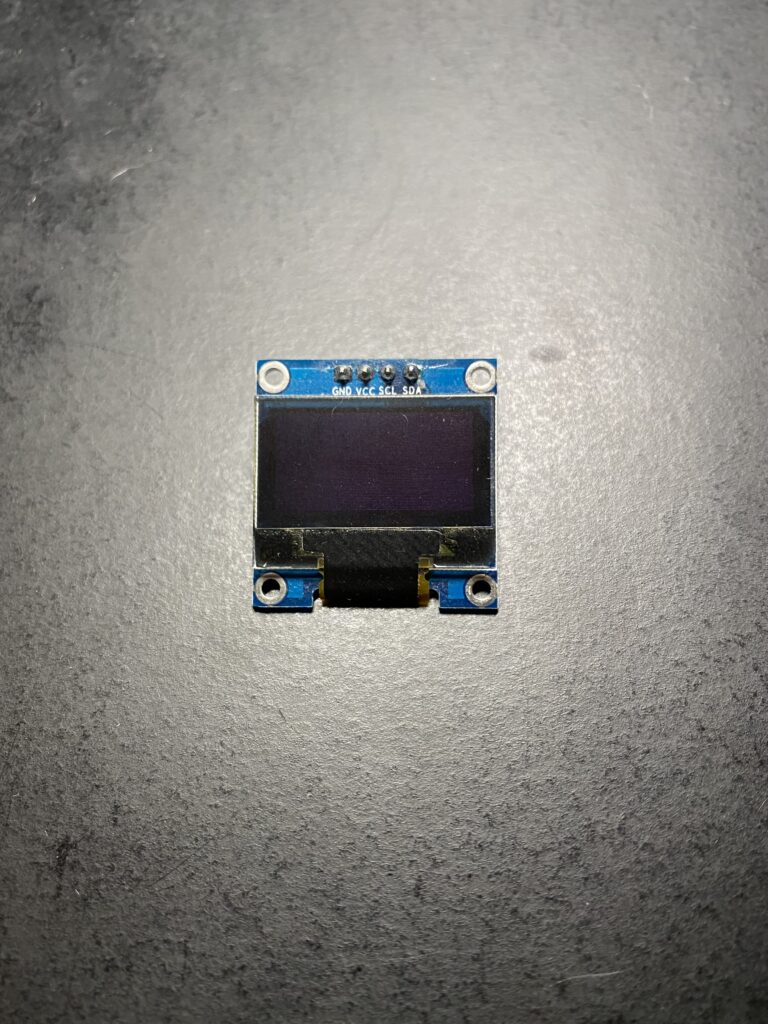
This week I spent some time exploring two different methods of synchronous serial communication: I2C and SPI. Since I didn’t have the specific modules in the class labs I made use of two modules that I did have including an SPI RFID Tag Reader and an I2C OLED 128×64 Pixel Display.
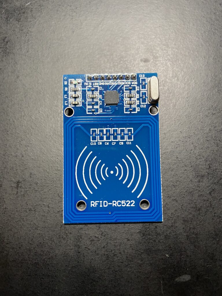
I have wanted to do work with RFID tags for a while now. RFID tags are especially interesting to me because they can store small amounts of data, be embedded below surfaces, and are powered by RFID readers and writers wirelessly. Though I am most familiar with using RFID for laundry cards, or building access, there are a range of other potential applications.
Looking at the two modules the RFID-RC522 operates at 13.56MHz, which is good for close range reading and writing to RFID tags, and has a 3.3V operating voltage. Conveniently I had also purchased a number of programable RFID tag stickers to use with the module.
The OLED display operates over I2C also at 3.3V. To make use of the display I utilized a library and some tutorials from Adafruit which I have included in the code at the bottom of this page.
Thinking about my parts I made a plan to use the RFID reader to read characters as data from RFID stickers with the Arduino, then display those characters on the OLED display.
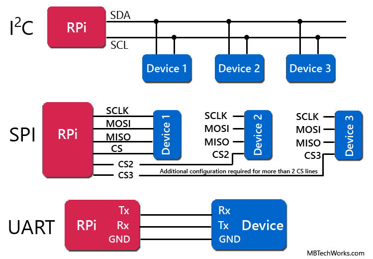
Once I was familiar with the parts I had to layout the circuit. Here is a helpful diagram comparing I2C, SPI, and UART synchronous serial communication wiring.
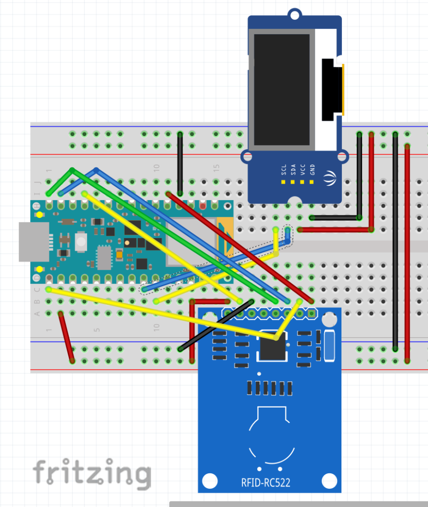
Thankfully the Arduino Nano 33 IoT I planned to use had many predefined pins for both the I2C and SPI connections that were necessary for the RFID and OLED modules. The outliers that would need to be defined in software were SDA and RST for the RFID module.
Here is a Fritzing diagram of the breadboard layout:
With the board setup my next question was how to program the RFID tags?
Included in the code at the bottom of this page is a section I have commented out for writing to the RFID tags. The tags are capable of storing 144 bytes of data, however the code below only makes use of a 16 byte buffer. This could stand to be even more efficient because I ultimately only used the first byte of data to write and read each character.
The final product with code below.
#include <SPI.h>
#include <MFRC522.h>
#include <Wire.h>
#include <Adafruit_GFX.h>
#include <Adafruit_SSD1306.h>

#define SCREEN_WIDTH 128 // OLED display width, in pixels
#define SCREEN_HEIGHT 64 // OLED display height, in pixels

// Declaration for an SSD1306 display connected to I2C (SDA, SCL pins)
#define OLED_RESET     4 // Reset pin # (or -1 if sharing Arduino reset pin)
Adafruit_SSD1306 display(SCREEN_WIDTH, SCREEN_HEIGHT, &Wire, OLED_RESET);

// RFID tag variables
byte letter = ' ';

#define SS_PIN          2
#define RST_PIN         9

MFRC522 mfrc522(SS_PIN, RST_PIN);  // Create MFRC522 instance
MFRC522::StatusCode status; //variable to get card status

byte buffer[18];  //data transfer buffer (16+2 bytes data+CRC)
byte size = sizeof(buffer);

uint8_t pageAddr = 0x06;  //In this example we will write/read 16 bytes (page 6,7,8 and 9).
                          //Ultraligth mem = 16 pages. 4 bytes per page.
                          //Pages 0 to 4 are for special functions.


void setup() {
  Serial.begin(9600);
  //while (!Serial){} // wait for serial port to connect
  Serial.println("RFID Reader with OLED Display Started");

  //RFID setup
  SPI.begin(); // Init SPI bus
  mfrc522.PCD_Init(); // Init MFRC522 card
  memcpy(buffer,"HELLO WORLD! ;-)",16);

  // SSD1306_SWITCHCAPVCC = generate display voltage from 3.3V internally
  if(!display.begin(SSD1306_SWITCHCAPVCC, 0x3C)) { // Display I2C address is 0x3C
    Serial.println(F("SSD1306 allocation failed"));
    for(;;); // Don't proceed, loop forever
  }

  // Show initial display buffer contents on the screen --
  // the library initializes this with and Adafruit splash screen.
  display.display();

}

void loop() {

  /* OLED Display */

  // Clear the buffer
  display.clearDisplay();

  testscrolltext();    // Draw scrolling text

  /* RFID Reader */

  // Look for new cards
  if ( ! mfrc522.PICC_IsNewCardPresent())
    return;

  // Select one of the cards
  if ( ! mfrc522.PICC_ReadCardSerial())
    return;

  // Write data ***********************************************
  /*
  for (int i=0; i < 4; i++) {
    //data is writen in blocks of 4 bytes (4 bytes per page)
    status = (MFRC522::StatusCode) mfrc522.MIFARE_Ultralight_Write(pageAddr+i, &buffer[i*4], 4);
    if (status != MFRC522::STATUS_OK) {
      Serial.print(F("MIFARE_Read() failed: "));
      Serial.println(mfrc522.GetStatusCodeName(status));
      return;
    }
  }
  Serial.println(F("MIFARE_Ultralight_Write() OK "));
  Serial.println();
  */

  // Read data ***************************************************
  Serial.println(F("Reading data ... "));
  //data in 4 block is readed at once.
  status = (MFRC522::StatusCode) mfrc522.MIFARE_Read(pageAddr, buffer, &size);
  if (status != MFRC522::STATUS_OK) {
    Serial.print(F("MIFARE_Read() failed: "));
    Serial.println(mfrc522.GetStatusCodeName(status));
    return;
  }

  Serial.print(F("Read data: "));
  //Dump a byte array to Serial
  for (byte i = 0; i < 16; i++) {
    Serial.write(buffer[i]);
    if(i == 0){
      letter = buffer[i];
    }
  }
  Serial.println();

  mfrc522.PICC_HaltA();

}


void testscrolltext(void) {
  display.clearDisplay();

  display.setTextSize(8); // Draw 2X-scale text
  display.setTextColor(SSD1306_WHITE);
  display.setCursor(45, 0);
  display.println(char(letter));
  display.display();      // Show initial text
  delay(100);

}


