Lab: Two-Way (Duplex) Serial Communication Using An Arduino and P5.js
In this lab I combined a number of capabilities to create a pointing and selecting device (mouse) that uses two-way (duplex) communication.
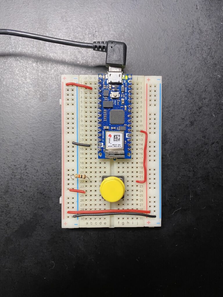
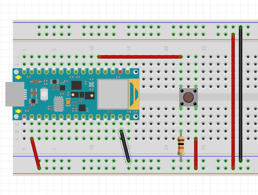
Here is the circuit I used along with a Fritzing diagram:
Code with some smoothing to the readings:
#include <Arduino_LSM6DS3.h> // This library reads sensor values from the Intertial Measurement Unit (IMU).

  // digital input
  const int buttonPin = 2;

  // buffer to smooth readings
  int xBuffer[] = {0,0,0};
  int yBuffer[] = {0,0,0};

void setup() {
  // configure the serial connection:
  Serial.begin(9600);
  // configure the digital input:
  pinMode(buttonPin, INPUT);
  // Initialize the IMU sensor
  if (!IMU.begin()) {
    Serial.println("Failed to initialize IMU!");
    while (true); // halt program
  }

  Serial.println("IMU initialized!");
}

void loop() {

  // Local variables for orientation data from IMU
  float aX, aY, aZ;
  float gX, gY, gZ;
  const char * spacer = ", ";

  // Try to read the IMU sensor
  if (
    IMU.accelerationAvailable()
    && IMU.gyroscopeAvailable()
  ) {
    IMU.readAcceleration(aX, aY, aZ);
    IMU.readGyroscope(gX, gY, gZ);

    // adjust the sensor values to be closer to 10bit analog reads
    aX = (aX + 1)*512;
    aY = (aY + 1)*512;

    // do some smoothing to reads
    aX = (xBuffer[0] + xBuffer[1] + xBuffer[2] + aX)/4;
    aY = (yBuffer[0] + yBuffer[1] + yBuffer[2] + aY)/4;

    // save new value to buffer
    xBuffer[2] = xBuffer[1];
    xBuffer[1] = xBuffer[0];
    xBuffer[0] = aX;
    yBuffer[2] = yBuffer[1];
    yBuffer[1] = yBuffer[0];
    yBuffer[0] = aY;

    // print the X rotation:
    Serial.print(aX);
    Serial.print(",");

    // print the y rotation:
    Serial.print(aY);
    Serial.print(",");

    // read the button:
    int sensorValue = digitalRead(buttonPin);
    // print the results:
    Serial.println(sensorValue);
  }
}
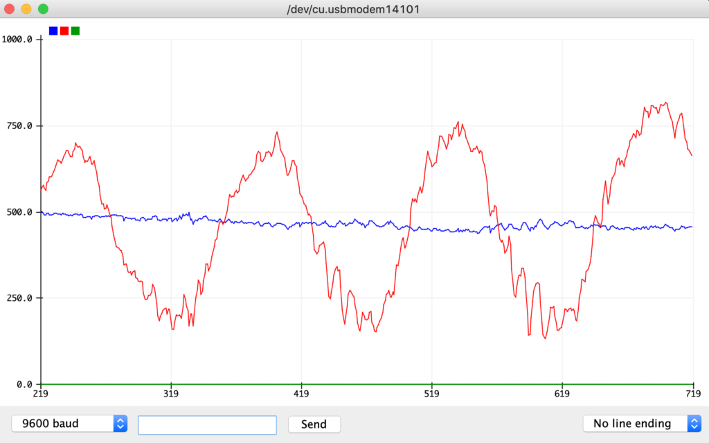
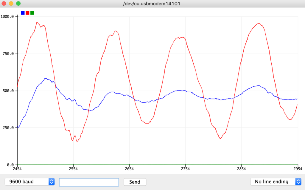
Taking a look at the X and Y axis IMU readings in the serial plotter I noticed there was quite a lot of noise and decided to implement a buffer that averages out the last four readings. Example of the difference here:
Now to use this serial output to control a P5 sketch I shifted to the code running on my computer that the Arduino was connected to. You can see the P5 sketch here.
With this function working I next modified the code for the Arduino to only send data after a “handshake” with the computer. The benefit of this approach is that it will only send data when requested and reduces the chance of a buffer overflow.
Here is the modified Arduino code:
#include <Arduino_LSM6DS3.h> // This library reads sensor values from the Intertial Measurement Unit (IMU).

  // digital input
  const int buttonPin = 2;

  // buffer to smooth readings
  int xBuffer[] = {0,0,0};
  int yBuffer[] = {0,0,0};

void setup() {
  // configure the serial connection:
  Serial.begin(9600);

  // Initialize the IMU sensor
  if (!IMU.begin()) {
    //Serial.println("Failed to initialize IMU!");
    while (true); // halt program
  }
  //Serial.println("IMU initialized!");

  while (Serial.available() <= 0) {
    Serial.println("hello"); // send a starting message
    delay(300);              // wait 1/3 second
  }
  // configure the digital input:
  pinMode(buttonPin, INPUT);

}

void loop() {

  // Local variables for orientation data from IMU
  float aX, aY, aZ;
  float gX, gY, gZ;
  const char * spacer = ", ";

  // Try to read the IMU sensor
  if (
    IMU.accelerationAvailable()
    && IMU.gyroscopeAvailable()
  ) {
    IMU.readAcceleration(aX, aY, aZ);
    IMU.readGyroscope(gX, gY, gZ);

    // adjust the sensor values to be closer to 10bit analog reads
    aX = (aX + 1)*512;
    aY = (aY + 1)*512;

    // do some smoothing to reads
    aX = (xBuffer[0] + xBuffer[1] + xBuffer[2] + aX)/4;
    aY = (yBuffer[0] + yBuffer[1] + yBuffer[2] + aY)/4;

    // save new value to buffer
    xBuffer[2] = xBuffer[1];
    xBuffer[1] = xBuffer[0];
    xBuffer[0] = aX;
    yBuffer[2] = yBuffer[1];
    yBuffer[1] = yBuffer[0];
    yBuffer[0] = aY;

    if (Serial.available() > 0) {

      // print the X rotation:
      Serial.print(aX);
      Serial.print(",");

      // print the y rotation:
      Serial.print(aY);
      Serial.print(",");

      // read the button:
      int sensorValue = digitalRead(buttonPin);
      // print the results:
      Serial.println(sensorValue);

    }
  }
}
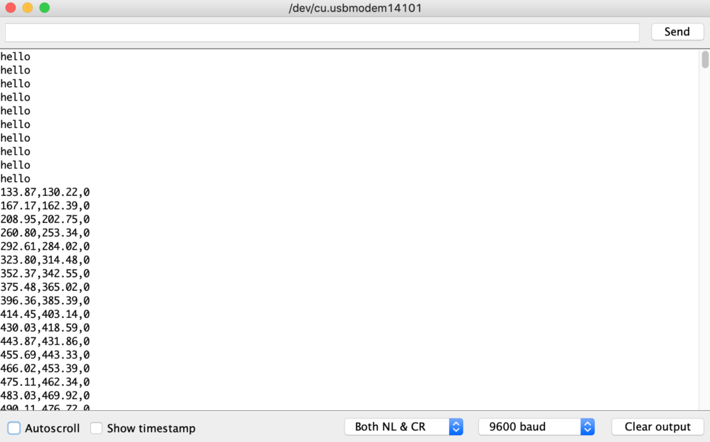
I did run into an issue with this arrangement where the “handshake” would cause a stream of values rather than a single set:
Finally I took what I learned in this lab and tried it out with my own sketch, this time using my Dodeca enclosure and mapping the movement to a 3D object in a P5.js sketch. Arduino code below.
#include <Arduino_LSM6DS3.h> // This library reads sensor values from the Intertial Measurement Unit (IMU).
#include "MadgwickAHRS.h" // This library generates Euler angle measures from the IMU.

  // digital input
  const int buttonPin = 2;

  // Initialize a Madgwick filter:
  Madgwick filter;

  // Set sensor's sample rate to 104 Hz to improve accuracy of Euler angle interpretations by Madgwick library
  const float sensorRate = 104.00;

  // buffer to smooth readings
  int xBuffer[] = {0,0,0};
  int yBuffer[] = {0,0,0};

  // LED indicator info
  int ledPin = 17;
  int brightness = 1;
  int fadeAmount = 1;

void setup() {
  // configure the serial connection:
  Serial.begin(9600);

  // Initialize the IMU sensor
  if (!IMU.begin()) {
    Serial.println("Failed to initialize IMU!");
    while (true); // halt program
  }

  // Start the filter to run at the sample rate
  filter.begin(sensorRate);

  Serial.println("IMU initialized!");

  // configure the digital input:
  pinMode(buttonPin, INPUT);

}

void loop() {

  pulseLED();

  // Local variables for orientation data from IMU
  float aX, aY, aZ;
  float gX, gY, gZ;
  const char * spacer = ", ";

  // Local variables for orientation from Madgwick library
  float roll, pitch, heading;

  // Try to read the IMU sensor
  if (
    IMU.accelerationAvailable()
    && IMU.gyroscopeAvailable()
  ) {
    IMU.readAcceleration(aX, aY, aZ);
    IMU.readGyroscope(gX, gY, gZ);

    // Update the filter, which computes orientation
    filter.updateIMU(gX, gY, gZ, aX, aY, aZ);

    // Print the heading, pitch and roll
    roll = filter.getRoll() + 180; // 180 to -180 y leaves x unchanged
    pitch = filter.getPitch() + 90; // 90 to -90 x leaves y unchanged

    // adjust the sensor values to be closer to 10bit analog reads
    //aX = (aX + 1)*512;
    //aY = (aY + 1)*512;

    // do some smoothing to reads
    pitch = (xBuffer[0] + xBuffer[1] + xBuffer[2] + pitch)/4;
    roll = (yBuffer[0] + yBuffer[1] + yBuffer[2] + roll)/4;

    // save new value to buffer
    xBuffer[2] = xBuffer[1];
    xBuffer[1] = xBuffer[0];
    xBuffer[0] = pitch;
    yBuffer[2] = yBuffer[1];
    yBuffer[1] = yBuffer[0];
    yBuffer[0] = roll;

    // print the X rotation:
    Serial.print(pitch);
    Serial.print(",");

    // print the y rotation:
    Serial.print(roll);
    Serial.print(",");

    // read the button:
    int sensorValue = digitalRead(buttonPin);
    // print the results:
    Serial.println(sensorValue);

  }
}

void pulseLED(){
  // Write brightness to LED
  analogWrite(ledPin, brightness);

  brightness = brightness + fadeAmount;
  // Reverse the direction of the fading at the ends of the fade
  if(brightness == 1 || brightness == 254)
  {
    fadeAmount = -fadeAmount ;
  }
  //Serial.print("fading LED to ");
  //Serial.println(brightness);
  delay(2);
}


