Lab: Servo Motor Control with an Arduino
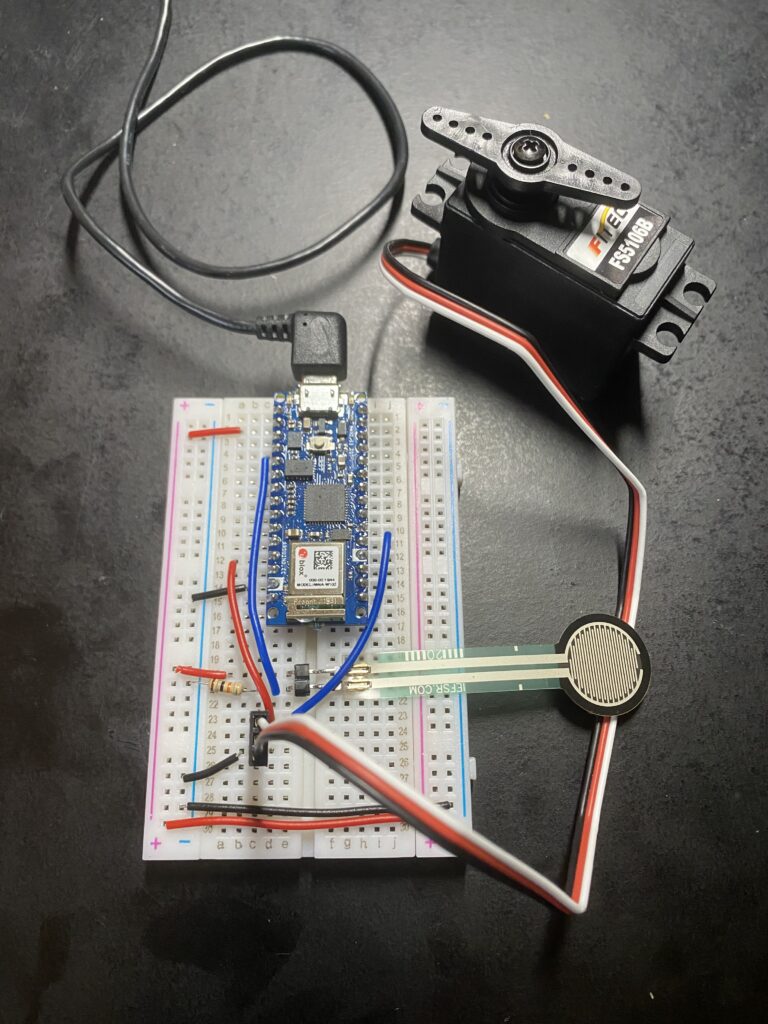
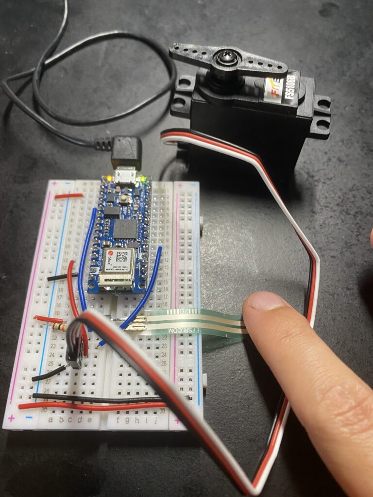
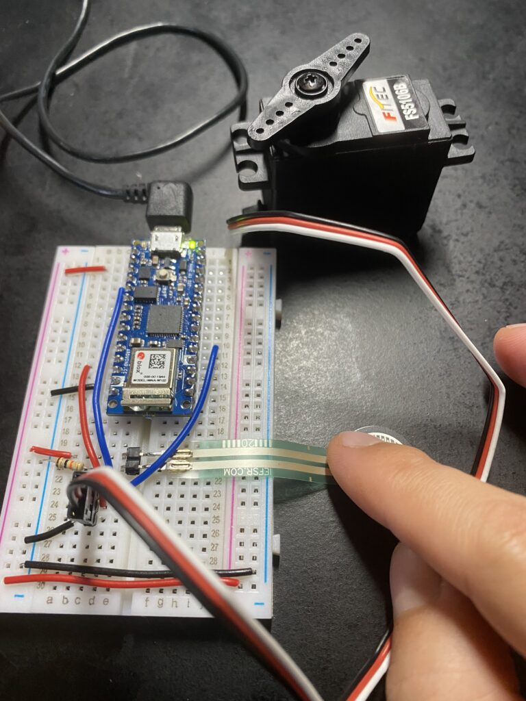
For this lab I set out to control a servo motor based on input from a force sensing resistor. Going into this I had some concerns about the ability of the Nano 33 IoT to supply the necessary voltage and current to power the FS5106B servo motor I had access to.
#include "Servo.h"      // include the servo library

Servo servoMotor;       // creates an instance of the servo object to control a servo
int servoPin = 3;       // Control pin for servo motor

void setup() {
  Serial.begin(9600);       // initialize serial communications
  servoMotor.attach(servoPin);  // attaches the servo on pin 3 to the servo object
}

void loop()
{
  int analogValue = analogRead(A0); // read the analog input
  Serial.println(analogValue);      // print it

  // if your sensor's range is less than 0 to 1023, you'll need to
  // modify the map() function to use the values you discovered:
  int servoAngle = map(analogValue, 0, 1023, 0, 179);

  // move the servo using the angle from the sensor:
  servoMotor.write(servoAngle);

  //delay(200);
}
Initially powering the servo from the Nano’s 3 volt rail resulted in no movement. This made sense considering the data sheet for the FS5106B servo specifies a minimum voltage of 4.8 volts. USB supplies 5 volts so shouldn’t I have access to that somewhere on the Nano 33? Reading on the Arduino site I learned I had to short the VBUS jumper on the back of the board to provide 5 volt power to the VUSB pin. After doing this moving the servo supply to the Nano’s VUSB pin did power up the servo and allow the force sensor readings to control it, however after a few seconds of movement a yellow light on the nano began to flash and motor movement stopped. Was the servo drawing too much current?
Looking back at the data sheet for the FS5106B servo the current at no load should be about 160mA. This is both less than the USB expected max load of 500mA and more than the DC Current per I/O Pin of 7mA listed on the Arduino site.
Another explanation may have to do with the Nano 33 IO pins not being 5 volt tolerant. Are the data and power lines on the servo separate? This is unclear to me. To avoid any potential damage to the board I will stop here for now.


