Measurement Project
After encouragement in class last week I did more research into flashing custom firmware to the Smart Plug I have been using to measure power draw for various items around my home. The default firmware and app combo had some severe limitations including limiting historical data to cumulative power use by day and also provided no method to export data. Fortunately I was able to overcome these limitations with some simple hardware hacking and custom firmware!
Devices like the one I am using are available from many different brand names and often under $10/unit. A conversation with my classmate Phil Caridi brought up that the huge variety of brands for these devices are likely using the same rebranded generic components.
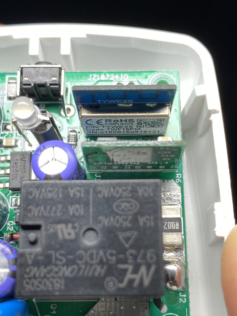
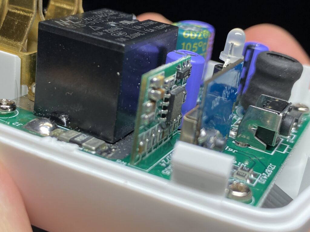
A peek inside one of my Smart Plugs revealed a TYWE2S module, which appeared to be operating as the brains of the device and is itself an ESP8266/ESP8265 WiFi module which is easily programmed using the Arduino IDE. Further research pointed me to a GitHub effort called Tuya-Convert as a means to upload custom firmware OTA to these generic modules, however it appears from recent forum posts that a vendor firmware update has broken this technique. So instead I went straight to the hardware hacking approach.
Forum posts here from user PeteKnight outline the steps to reprogramming the TYWE2S module and provide a useful starting point with Arduino code for OTA updates.
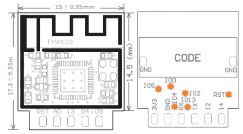
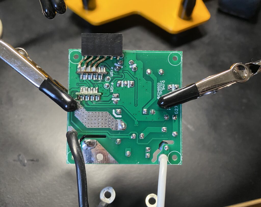
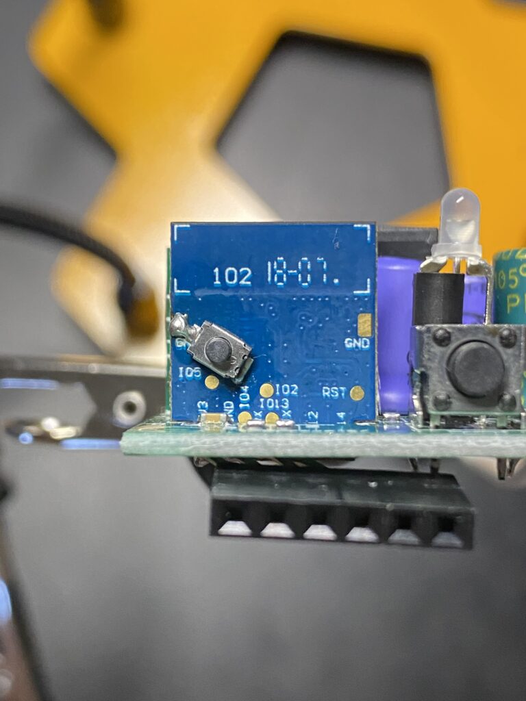
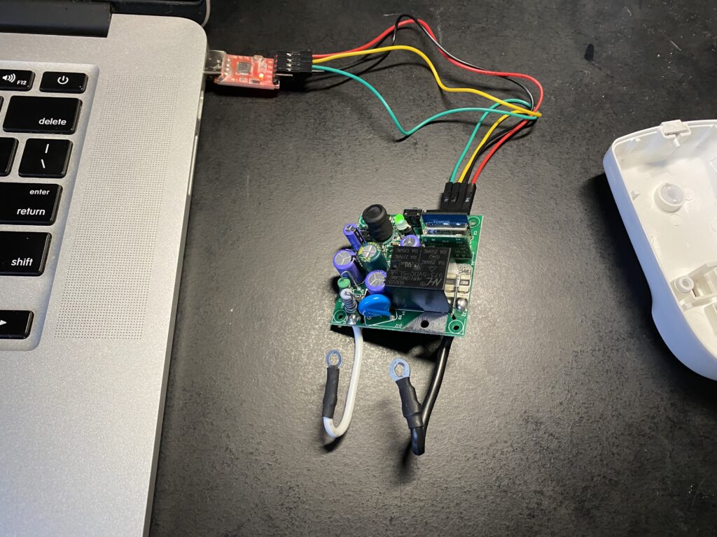
Referencing the diagram pinout above for the TYWE2S my first step was soldering a header to the 3.3V, GND, RX, and TX pins.
Next I soldered a small push button switch directly on the TYWE2S module between GND and the contact 100, which when pressed during boot will put the ESP module into programming mode.
Usually efforts like this take some troubleshooting but reprogramming the board through a USB to TTL connector with the Arduino IDE went smoothly (just be sure not to have the Smart Plug connected to mains power!).
The Arduino code (included at the bottom of this page) uses a few libraries you will need to download that are available in the Arduino Libraries Manager including ESP8266Wifi, Blynk (from vshymanskyy), and HLW8012 (from xoseperez).
An unmarked IC in the Smart Plug is responsible for measuring power use and communicating that to the ESP module. My best guess is that this is an HLW8012 based on other user comments and the pinout. Modifying the custom firmware to include code from HLW8012 (from xoseperez) seemed to confirm this, though the same code mentioned 230V mains and returned readings with half of the expected wattage. As a quick fix I adjusted the value for VOLTAGE_RESISTOR_UPSTREAM to match results from an unmodified TopGreener Smart Outlet.
Presto chago! Custom firmware is up and running!
To control the device and store data I am making use of Blynk.io. It is certainly possible to setup a custom web server and by no means is it a requirement to use this service but it helped to make this process a heck of a lot easier.
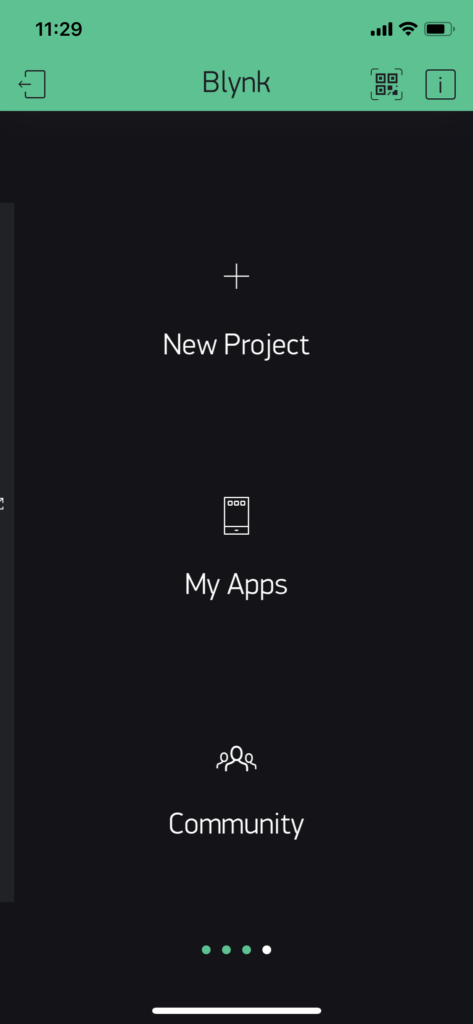
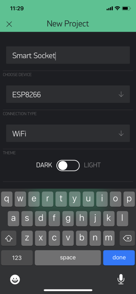
After downloading the Blynk smartphone app and providing an email address to create an account I was able to create a “New Project” which provides a unique Authentication Token over email to place in the Arduino code.
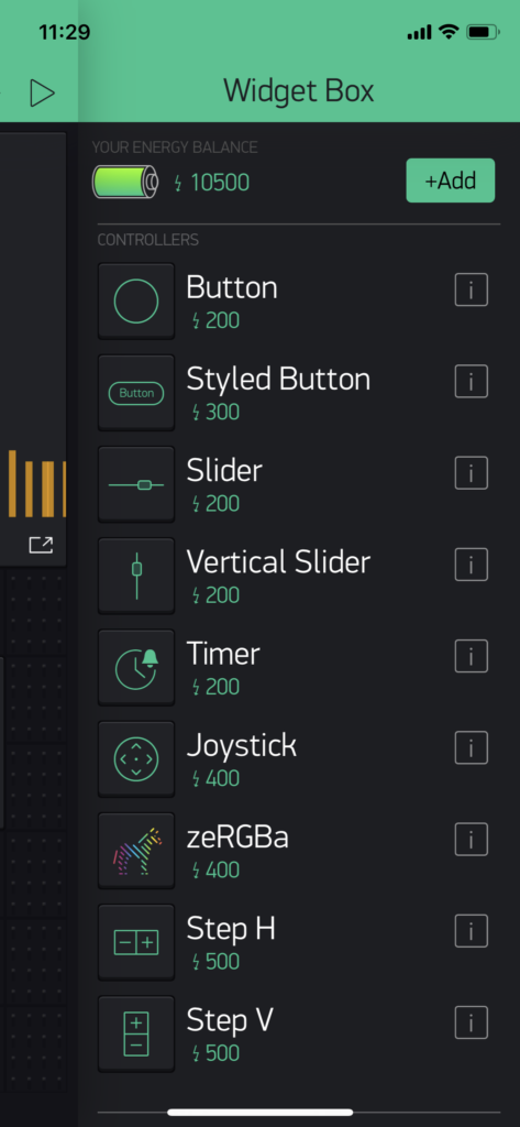
From here it is a matter of adding in various widgets from the “Widget Box” including categories such as controllers, displays, notifications, device management, etc.
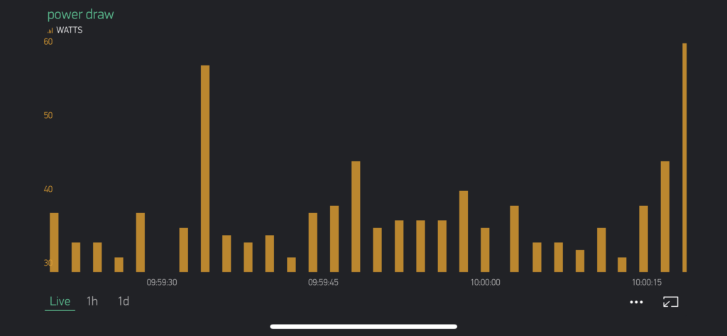
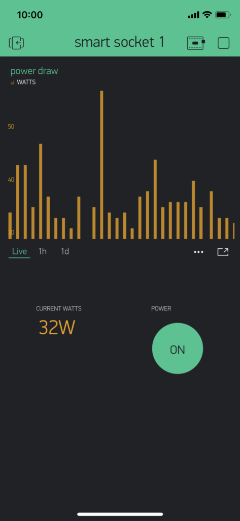
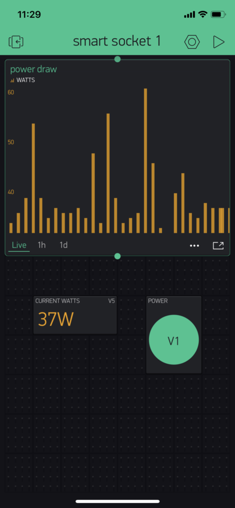
I set mine up to include a “Button” to control power (ON/OFF) linked to Virtual Pin 1 in the Arduino Code and two displays for Virtual Pin 5 where the Arduino Code is sharing real time wattage: both a “Labeled Display” to show current wattage and a “SuperChart” to record the real time data which is conveniently available to download as a CSV file.
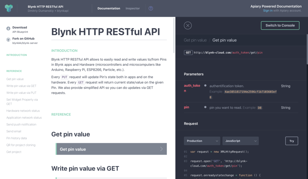
Taking this all one step further Blynk also provides access to an HTTP RESTful API making it easy to access data from the Smart Plug in real time.
// "Smart Plug" for "TopGreener 15A Smart Outlet" by Brandon Roots
// Based on Blynk + OTA Code for "W-DE004 WIFI SMART SOCKET" by Pete Knight

// Arduino IDE Upload Settings
// Board:            "Generic ESP8266 Module"
// Flash Mode:       "DOUT"
// Flash Size:       "1M (No SPIFFS)"
// Debug Port:       "Disabled"
// Debug Level:      "None"
// IwIP Variant:     "v1.4 Prebuilt"
// Reset Method:     "ck"
// Crystal Frequency "26 MHz"
// Flash Frequency:  "40 MHz"
// CPU Frequency:    "80MHz"
// Upload Speed:     "115200"

// Blynk App Project Setup:
// Add a Button widget connected to Virtual Pin V1
// Set button widget to Switch mode
// Add a Labeled Display and Virtual Chart to Pin V5 to monitor Wattage

// Notes:
// The wifi socket uses GPIO3 for the physical button. This is the hardware TX pin on the ESP8266, so SERIAL OUTPUT FOR DEBUGGING WILL NOT WORK !
// Please do not add Serial.begin() to this sketch

// TYWE2S Module Pinout
// Pin 1 --> RST --> I/O --> External Reset
// Pin 2 --> AD --> AI --> ADC Terminal (10-bits SAR ADC)
// Pin 3 --> 13 --> I/O --> GPIO_13
// Pin 4 --> 04 --> I/O --> GPIO_04
// Pin 5 --> 05 --> I/O --> GPIO_05
// Pin 6 --> 3V3 --> P --> Supply Voltage (3.3V)
// Pin 7 --> GND --> P --> Ground
// Pin 8 --> RX --> I/O --> UART0_RXD
// Pin 9 --> TX --> I/O --> UART0_TXD
// Pin 10 --> 12 --> I/O --> GPIO_12
// Pin 11 --> 14 --> I/O --> GPIO_14

#include <ArduinoOTA.h>
#include <ESP8266WiFi.h>
#include <BlynkSimpleEsp8266.h>
#include <Ticker.h>                  // Used to flash the LED in non-blocking mode
#include <HLW8012.h>

char auth[] = "Your authentication token from Blynk"; // Free for non-commercial use, download the app to get started
char ssid[] = "Your WiFi SSID";
char pass[] = "Your WiFi Password";
char OTAhost[] = "Smart Socket 1"; // A name to identify in the Arduino IDE


#define RELAY1    14                 // Wi-Fi Switch relay and Blue LED is connected to GPIO 14 (LOW(0)=0ff, HIGH(1)=On)
#define buttonPin  3                 // Wi-Fi Switch pushbutton is connected to GPIO 3 (LOW(0)=Pushed, HIGH(1)=Released)
#define GreenLED  13                 // Wi-Fi Switch Green LED is connected to GPIO 13 (LOW(0)=0n, HIGH(1)=Off)

// HLW8012 Power Sensor
#define CF_PIN     4                 //GPIO4=CF(hlw8012)
#define CF1_PIN    5                 //GPIO5=CF1(hlw8012)
#define SEL_PIN   12                 //GPIO12=SEL(hlw8012)


int RELAY1_State;                    // Used to track the current Relay state
int reading = HIGH;                  // Used in the switch debounce routine
int buttonState=HIGH;                // The current button state is released (HIGH)
int lastButtonState = HIGH;          // The last button state is also relesed (HIGH) - Used in debounce routine
unsigned long lastDebounceTime = 0;  // The time in Millis that the output pin was toggled - Used in debounce routine
unsigned long debounceDelay = 20;    // The debounce delay; increase if you get multiple on/offs when the physical button is pressed

Ticker greenticker;                   // Create and instance of Ticker called greenticker
BlynkTimer timer;                    // Create and instance of BlynkTimer called timer


// Check values every 2 seconds
#define UPDATE_TIME                     2000

// Set SEL_PIN to HIGH to sample current
// This is the case for Itead's Sonoff POW, where a
// the SEL_PIN drives a transistor that pulls down
// the SEL pin in the HLW8012 when closed
#define CURRENT_MODE                    HIGH

// These are the nominal values for the resistors in the circuit
// * The CURRENT_RESISTOR is the 1milliOhm copper-manganese resistor in series with the main line
// * The VOLTAGE_RESISTOR_UPSTREAM are the 5 470kOhm resistors in the voltage divider that feeds the V2P pin in the HLW8012
// * The VOLTAGE_RESISTOR_DOWNSTREAM is the 1kOhm resistor in the voltage divider that feeds the V2P pin in the HLW8012
#define CURRENT_RESISTOR                0.001
#define VOLTAGE_RESISTOR_UPSTREAM       ( 2 * 470000 ) // 120V Mains
// #define VOLTAGE_RESISTOR_UPSTREAM       ( 5 * 470000 ) // Real: 2280k for 230V mains
#define VOLTAGE_RESISTOR_DOWNSTREAM     ( 1000 ) // Real 1.009k

HLW8012 hlw8012;


void unblockingDelay(unsigned long mseconds) {
    unsigned long timeout = millis();
    while ((millis() - timeout) < mseconds) delay(1);
}

void calibrate() {

    // Let's first read power, current and voltage
    // with an interval in between to allow the signal to stabilise:

    hlw8012.getActivePower();

    hlw8012.setMode(MODE_CURRENT);
    unblockingDelay(2000);
    hlw8012.getCurrent();

    hlw8012.setMode(MODE_VOLTAGE);
    unblockingDelay(2000);
    hlw8012.getVoltage();

    // Calibrate using a 60W bulb (pure resistive) on a 120V line
    hlw8012.expectedActivePower(60.0);
    hlw8012.expectedVoltage(120.0);
    hlw8012.expectedCurrent(60.0 / 120.0);

}

void setup()
{
  pinMode(RELAY1, OUTPUT);
  pinMode(GreenLED, OUTPUT);
  pinMode(buttonPin, INPUT);

  digitalWrite(RELAY1, LOW);                // Turn the Relay off
  digitalWrite(GreenLED, HIGH);              // Turn the Green LED off

  greenticker.attach(0.1, greentick);         // start greenticker with 0.1 second flashes to indicate we're trying to connect to WiFi/Blynk
  WiFi.mode(WIFI_STA);
  Blynk.begin(auth, ssid, pass);
  while (Blynk.connect() == false) {}       // Dont proceed until we're connected to WiFi/Blynk
  greenticker.detach();                      // Stop the greenticker now we're connected
  digitalWrite(GreenLED, HIGH);              // Turn the Green LED Off if it was previoulsy On

  Blynk.virtualWrite(V1, 0);                // If the App switch widget is On, turn it Off

  ArduinoOTA.onError([](ota_error_t error) { ESP.restart(); });
  ArduinoOTA.setHostname(OTAhost);
  ArduinoOTA.begin();

  timer.setInterval(10L, CheckButtonState); // Timer to check the physical button every 10ms

    // Close the relay to switch on the load
    pinMode(RELAY1, OUTPUT);
    digitalWrite(RELAY1, HIGH);

    // Initialize HLW8012
    // void begin(unsigned char cf_pin, unsigned char cf1_pin, unsigned char sel_pin, unsigned char currentWhen = HIGH, bool use_interrupts = false, unsigned long pulse_timeout = PULSE_TIMEOUT);
    // * cf_pin, cf1_pin and sel_pin are GPIOs to the HLW8012 IC
    // * currentWhen is the value in sel_pin to select current sampling
    // * set use_interrupts to false, we will have to call handle() in the main loop to do the sampling
    // * set pulse_timeout to 500ms for a fast response but losing precision (that's ~24W precision :( )
    hlw8012.begin(CF_PIN, CF1_PIN, SEL_PIN, CURRENT_MODE, false, 500000);

    // These values are used to calculate current, voltage and power factors as per datasheet formula
    // These are the nominal values for the Sonoff POW resistors:
    // * The CURRENT_RESISTOR is the 1milliOhm copper-manganese resistor in series with the main line
    // * The VOLTAGE_RESISTOR_UPSTREAM are the 5 470kOhm resistors in the voltage divider that feeds the V2P pin in the HLW8012
    // * The VOLTAGE_RESISTOR_DOWNSTREAM is the 1kOhm resistor in the voltage divider that feeds the V2P pin in the HLW8012
    hlw8012.setResistors(CURRENT_RESISTOR, VOLTAGE_RESISTOR_UPSTREAM, VOLTAGE_RESISTOR_DOWNSTREAM);

    //calibrate();
}


void loop()
{
  Blynk.run();
  ArduinoOTA.handle();
  timer.run();


  // HLW8012 Power Monitoring

  static unsigned long last = millis();

    // This UPDATE_TIME should be at least twice the minimum time for the current or voltage
    // signals to stabilize. Experimentally that's about 1 second.
    if ((millis() - last) > UPDATE_TIME) {

        last = millis();

        Blynk.virtualWrite(V5, hlw8012.getActivePower()); // Active Power (W)
        Blynk.virtualWrite(V6, hlw8012.getVoltage()); // Voltage (V)
        Blynk.virtualWrite(V7, hlw8012.getCurrent()); // Current (A)
        Blynk.virtualWrite(V8, hlw8012.getApparentPower()); // Apparent Power (VA)
        Blynk.virtualWrite(V9, (int) (100 * hlw8012.getPowerFactor())); // Power Factor (%)


        // When not using interrupts we have to manually switch to current or voltage monitor
        // This means that every time we get into the conditional we only update one of them
        // while the other will return the cached value.
        hlw8012.toggleMode();

    }
}


BLYNK_WRITE(V1)                             // This code is triggered when the App button state changes
{
  int pinValue = param.asInt();             // Assign incoming value from pin V1 to a variable

  if (pinValue==1)                          // Do this if it was an On command from the Button widget in the App
  {
    digitalWrite(RELAY1, HIGH);             // Turn the relay On
    RELAY1_State = HIGH;                    // Keep track of the relay state
    digitalWrite(GreenLED, LOW);             // Turn the LED On
  }
  else                                      // Else do this if it was an Off command from the Button widget in the App
  {
    digitalWrite(RELAY1, LOW);              // Turn the relay Off
    RELAY1_State = LOW;                     // Keep track of the relay state
    digitalWrite(GreenLED, HIGH);            // Turn the LED Off
  }
}


void greentick() // Non-blocking ticker for Green LED
{
  //toggle state
  int state = digitalRead(GreenLED);         // get the current state of the GreenLED pin
  digitalWrite(GreenLED, !state);            // set pin to the opposite state
}


void CheckButtonState()
{
  reading = digitalRead(buttonPin);         // read the state of the physical switch
  if (reading != lastButtonState)
  {
    lastDebounceTime = millis();            // Start the debounce timer
  }

  if ((millis() - lastDebounceTime) > debounceDelay)
  {
    if (reading != buttonState)             // We get here if the physical button has been in the same state for longer than the debounce delay
    {
      buttonState = reading;

      if (buttonState == LOW)               // only toggle the power if the new button state is LOW (button pressed)
      {
        RELAY1_State = !RELAY1_State;
        if (RELAY1_State==HIGH)             // The physical button press was an instruction to turn the power On
        {
          digitalWrite(RELAY1, HIGH);       // Turn the relay On
          digitalWrite(GreenLED, LOW);       // Turn the LED On
          Blynk.virtualWrite(V1, 1);        // Turn the App button widget On
        }
        else                                // The physical button press was an instruction to turn the power Off
        {
          digitalWrite(RELAY1, RELAY1_State);  // Turn the relay Off
          digitalWrite(GreenLED, HIGH);         // Turn the LED Off
          Blynk.virtualWrite(V1, 0);           // Turn the App button widget Off
        }
      }
    }
  }
  lastButtonState = reading;                // Update lastButtonState for use next time around the loop
}
