Lab: Using a Transistor to Control High Current Loads with an Arduino
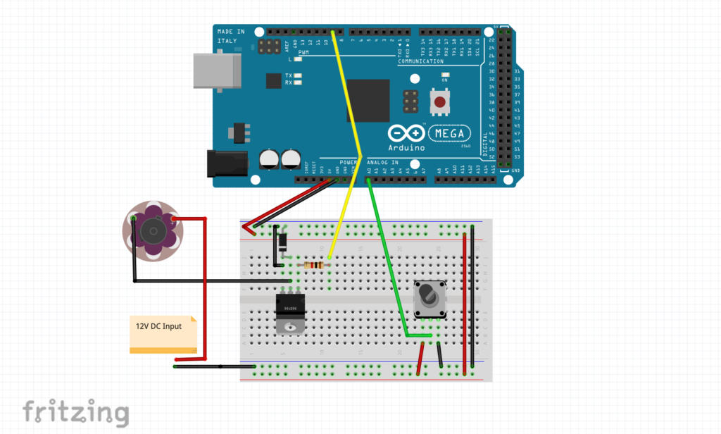
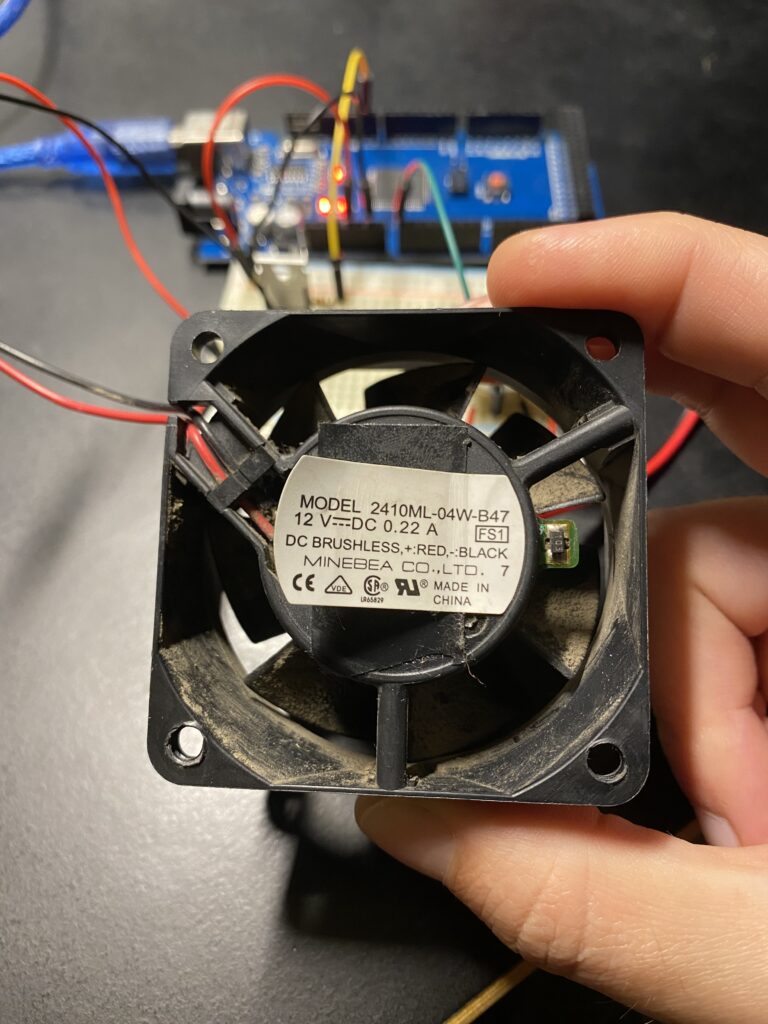
This week in Physical Computing we learned about controlling devices that require more current than can be provided by an Arduino directly. Because Arduino pins are limited to supplying 10mA it is necessary to provide additional power externally for high current peripherals. To try this out I put to use a DC fan I pulled from an old computer that requires 220mA to run.
My diagram and assembled breadboard:
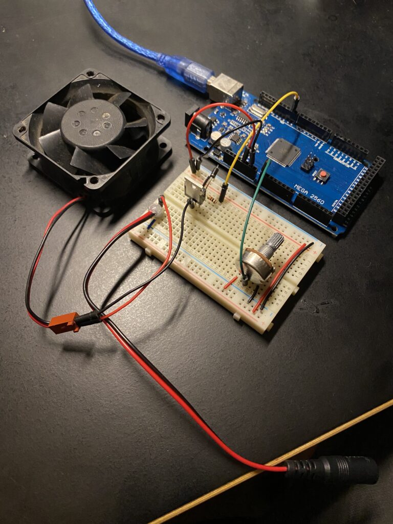
After wiring everything up I ran the sample code below and success! The fan runs.
const int transistorPin = 9;    // connected to the base of the transistor

 void setup() {
   // configure the serial connection:
   Serial.begin(9600);
   // set  the transistor pin as output:
   pinMode(transistorPin, OUTPUT);
 }

 void loop() {
   // read the potentiometer:
   int sensorValue = analogRead(A0);
   // map the sensor value to a range from 0 - 255:
   int outputValue = map(sensorValue, 0, 1023, 0, 255);
   Serial.println(outputValue);
   // use that to control the transistor:
   analogWrite(transistorPin, outputValue);
 }
While running this code something I noticed is that the motor only runs when the analogWrite value is 255, or full on the potentiometer. At all other values the motor would turn off. My guess is that this has something to do with the frequency of the PWM function and combination with this particular motor.
My gut feeling on this was that a slower on/off cycle than the PWM pin was operating at might work. Modify the code to include a delay of variable length allowed for slower speeds on the fan.
Is this ok for the motor? I’m not sure. Thankfully this is a junk shelf fan 🙂
const int transistorPin = 9;    // connected to the base of the transistor

 void setup() {
   // configure the serial connection:
   Serial.begin(9600);
   // set  the transistor pin as output:
   pinMode(transistorPin, OUTPUT);
 }

 void loop() {
   // read the potentiometer:
   int sensorValue = analogRead(A0);
   // map the sensor value to a range from 0 - 255:
   int outputValue = map(sensorValue, 0, 1023, 0, 255);
   Serial.println(outputValue);
   // use that to control the transistor:
   analogWrite(transistorPin, 255);
   delay(outputValue);
   analogWrite(transistorPin, 0);
 }


