Project 1: Dodeca – Part 1
Over the last week I had the pleasure of getting to know my classmate Mai. From our initial video call we brainstormed ideas for our first project in Physical Computing. Mai expressed interest in creating something musical but expressed concern that she didn’t have much of a background in music theory. I happened to have experience playing piano and guitar, so this struck me as a great idea for a collaboration. I have always found the relationship between shapes and musical scales curious and suggested that the IMU sensor inside of a geometric shape could be good to pair with tone output.
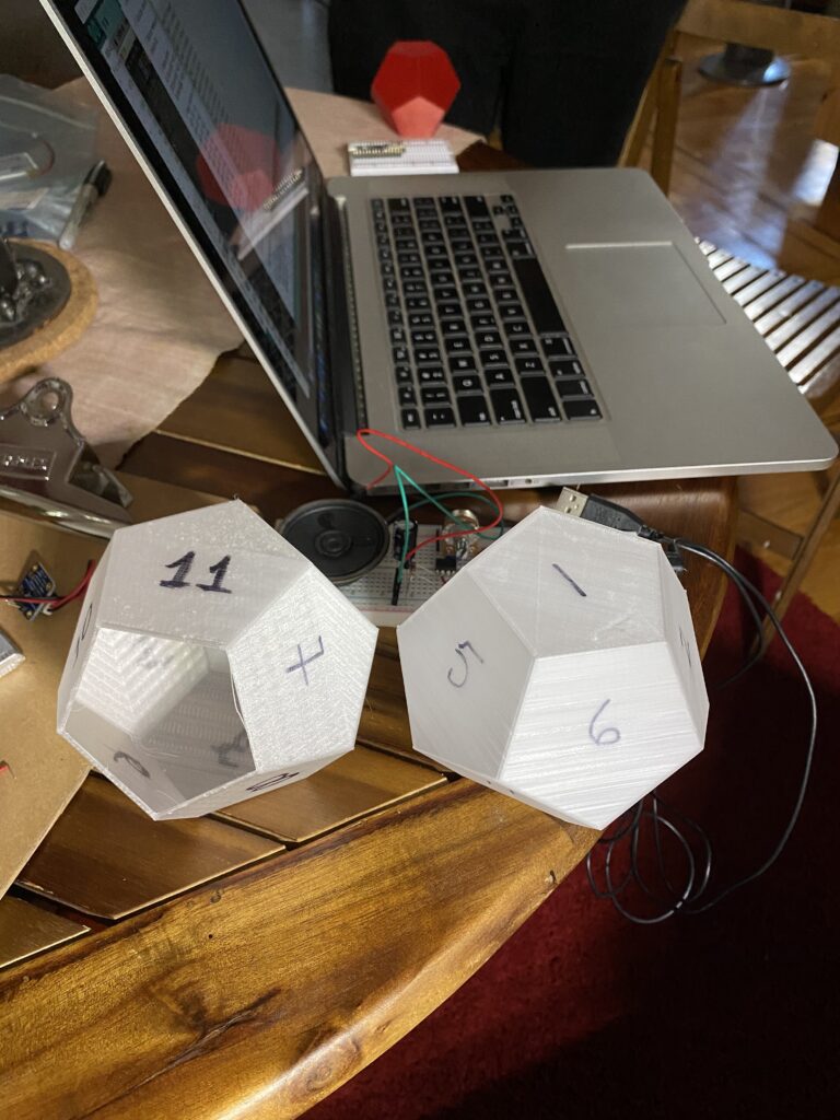
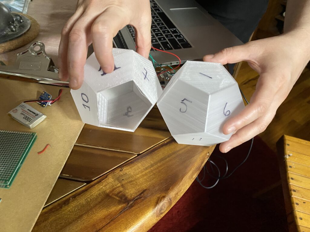
Together we came to the goal to create a musical device in the shape of a dodecahedron, which is a three dimensional shape consisting of twelve facets of equally sized pentagons.
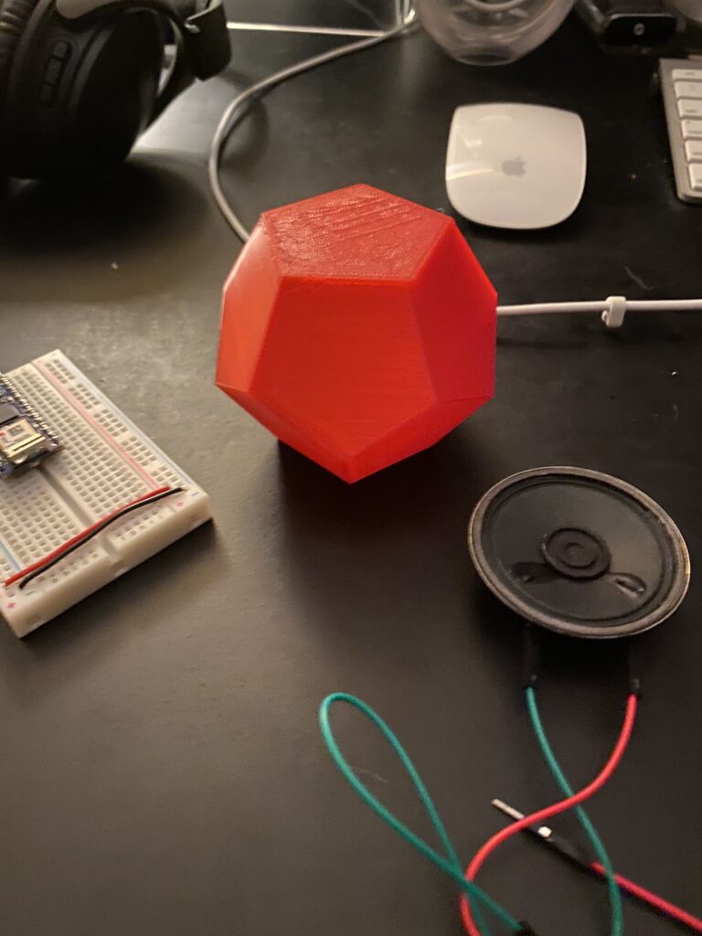
A test 3D print in PLA
We had a number of initial questions going into this project. From a coding standpoint how were we going to take measurements from the IMU sensor? Then what process could we use to translate those measurements into tones and map them to our physical object? Also in parallel to the coding how were we going to construct this object?
Our work this first week focused largely on designing and constructing a prototype circuit while also fabricating an initial prototype housing.
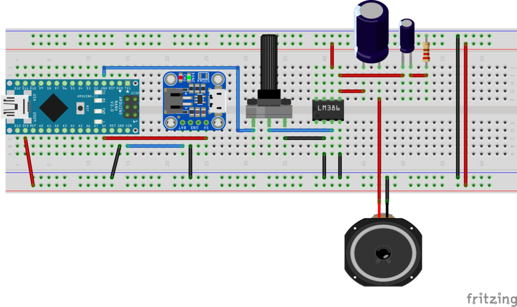
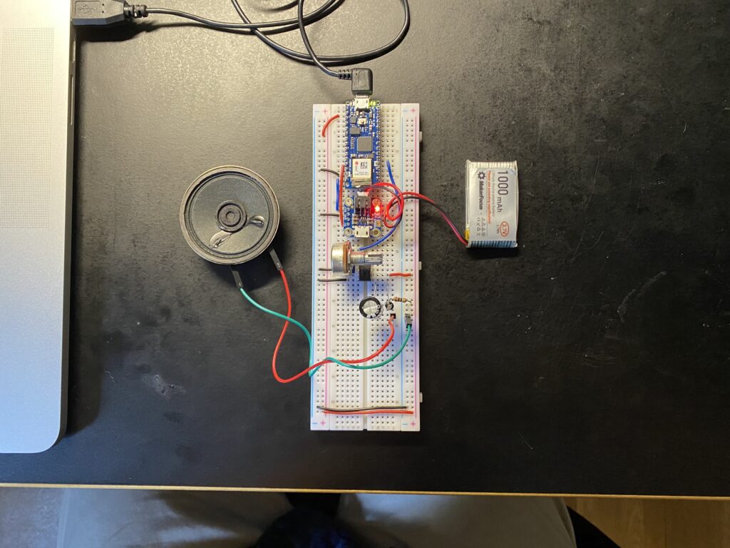
Our V1 circuit design made use of a couple of items outside of the class kit. From our lab exercises I had noticed that the speaker powered directing from the Arduino PWM pins has no volume control and would be too quiet, so some quick Googling found the LM386 IC as a cheap audio amplifier. Additionally we had discussed wanting the object to be self contained so having a rechargeable battery and battery charging circuit would be necessary. This lead to the Adafruit Micro-Lipo charging circuit.
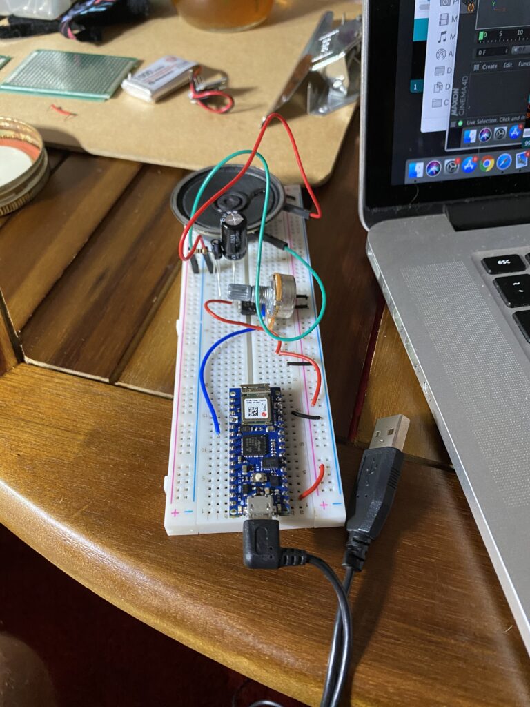
Here is the initial bread board all wired up without the battery elements:
Getting the initial circuit running ended up involving a few different libraries and digging through a bunch of sample code. This essentially broke down into the following processes:
1) Read the IMU sensor.
2) Have a matrix of 3D points correlating to the real life dodecahedron stored in the Arduino program.
3) Use some math magic on the Arduino to calculate rotating those 3D points around the X, Y, and Z axis based on the IMU reading.
4) Determine what facet is currently facing up based on the new point locations.
5) Map the facet to a tone.
6) Play tone.
7) Repeat.
This all worked out into the code below as a functioning prototype circuit. I will explain this all further in my next journal entry!
#include <Arduino_LSM6DS3.h>
#include <BasicLinearAlgebra.h>
#include <Geometry.h>
#include "pitches.h"

  // Points representing center of 12 facets of a dodecahedron in 3D space, 13-24 map to transforms
  Point p1, p2, p3, p4, p5, p6, p7, p8, p9, p10, p11, p12, p13, p14, p15, p16, p17, p18, p19, p20, p21, p22, p23, p24;

  // Major pentatonic scale
  int notes[] = {
    NOTE_AS5, NOTE_GS5, NOTE_FS5, NOTE_DS5, NOTE_CS5, NOTE_AS4, NOTE_GS4, NOTE_FS4, NOTE_DS4, NOTE_CS4, NOTE_AS3, NOTE_GS3
  };

  // Track which facet is facing up
  int lastUpwardFacet = 0;

void setup() {
  Serial.begin(9600);

  if (!IMU.begin()) {
    Serial.println("Failed to initialize IMU!");
    while (true); // halt program
  }
  Serial.println("IMU initialized!");

  // Map values to points in X(), Y() & Z() of dodecahedron with radius of 1 - found these values by making an object in Cinema 4D
  p1.X() = 0;
  p1.Y() = 0.795;
  p1.Z() = 0.058;

  p2.X() = 0;
  p2.Y() = 0.304;
  p2.Z() = -0.737;

  p3.X() = 0.645;
  p3.Y() = 0.397;
  p3.Z() = -0.245;

  p4.X() = 0.467;
  p4.Y() = 0.339;
  p4.Z() = 0.549;

  p5.X() = -0.467;
  p5.Y() = 0.339;
  p5.Z() = 0.549;

  p6.X() = -0.645;
  p6.Y() = 0.397;
  p6.Z() = -0.245;

  p7.X() = -0.467;
  p7.Y() = 0.339;
  p7.Z() = -0.549;

  p8.X() = 0.467;
  p8.Y() = 0.339;
  p8.Z() = -0.549;

  p9.X() = 0.645;
  p9.Y() = -0.397;
  p9.Z() = 0.245;

  p10.X() = 0;
  p10.Y() = -0.304;
  p10.Z() = 0.737;

  p11.X() = -0.645;
  p11.Y() = -0.397;
  p11.Z() = 0.245;

  p12.X() = 0;
  p12.Y() = -0.795;
  p12.Z() = -0.058;


}

void loop() {

  float aX, aY, aZ;
  //float gX, gY, gZ;
  const char * spacer = ", ";

  if (
    IMU.accelerationAvailable()
    && IMU.gyroscopeAvailable()
  ) {
    IMU.readAcceleration(aX, aY, aZ);
    //IMU.readGyroscope(gX, gY, gZ);

    // Calculate rotation of 12 points in dodeca

    // Rotation represents a rotated coordinate frame (a set of x/y/z axes) expressed with respect to a base frame.
    Rotation R1;

    // Rotate points...
    R1.RotateX(aX * M_PI_2);
    R1.RotateY(aY * M_PI_2);
    R1.RotateZ(aZ * M_PI_2);

    // Apply rotations to second set of points
    p13 = R1 * p1;
    p14 = R1 * p2;
    p15 = R1 * p3;
    p16 = R1 * p4;
    p17 = R1 * p5;
    p18 = R1 * p6;
    p19 = R1 * p7;
    p20 = R1 * p8;
    p21 = R1 * p9;
    p22 = R1 * p10;
    p23 = R1 * p11;
    p24 = R1 * p12;

    // Check which point+facet has largest Y value and is therefore UP
    float pointValuesY[12] = {p13.Y(), p14.Y(), p15.Y(), p16.Y(), p17.Y(), p18.Y(), p19.Y(), p20.Y(), p21.Y(), p22.Y(), p23.Y(), p24.Y()};

    //Serial.println(p13.Y());
    //Serial.println(pointValuesY[0]);

    float maximumValueY[2] = {pointValuesY[0], 0};

    for (int i = 1; i < 12; i++) {
      if (pointValuesY[i] > maximumValueY[0]) {
        maximumValueY[0] = pointValuesY[i];
        maximumValueY[1] = i;
      }
    }

    int upwardFacet = maximumValueY[1];

    if (lastUpwardFacet != upwardFacet) {

      // Do some things if a new facet is facing up
      Serial.print("Facet ");
      Serial.print(upwardFacet+1);
      Serial.println(" is facing up");

      // Make a sound mapped to this point+facet
      tone(2, notes[upwardFacet], 500);
      //noTone(8);

      // Record new upward facet
      lastUpwardFacet = upwardFacet;

      //Serial.print(aX); Serial.print(spacer);
      //Serial.print(aY); Serial.print(spacer);
      //Serial.println(aZ); Serial.print(spacer);
      //Serial.print(gX); Serial.print(spacer);
      //Serial.print(gY); Serial.print(spacer);
      //Serial.println(gZ);
       //delay(1000);

    }

    delay(100);
  }
}