Lab: Setting Up A Breadboard
For this lab for Physical Computing I reviewed some of the basics surrounding use of a breadboard and setting it up with a 5-volt voltage regulator. A breadboard is a very convenient way to temporarily assemble circuits without any of the mess or effort of soldering. The holes in the top of the board align with metal strips on the back side that are electrically conductive. Fortunately I already had most of these parts laying around my office from past work.
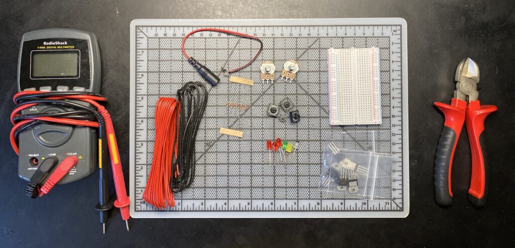
The parts that I will be using for this and the next couple of lab assignments.
Buttons, wires, resistors, LEDS, barrel connectors, voltage regulators, AC/DC adaptors, breadboard, all familiar from past projects. So here we go!

Looking at the label on my AC/DC power adapter it is rated for 12-volts, which appears to be within specification for the 7805 voltage regulator’s 9-12 volt range. 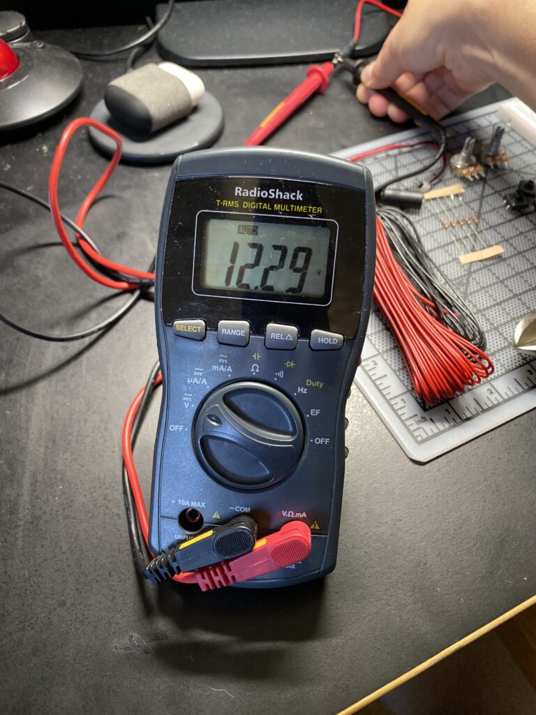
Using my multi-meter I tested my power source and read 12 volts.
My first step was to confirm that my power adapter is providing the correct voltage. Reading the voltage with my multimeter confirms that it is providing 12 volts. I purchased this high amerage power supply a while back for a project with hundreds of LEDs and am glad to put it to use again.
For the next step I went ahead and added a 7805 voltage regulator to the breadboard. This component drops input voltage from a range of 9 to 12 volts down to 5 volts. Typically I have used switching regulators, or buck converters, to achieve the same function. They are more power efficient than these linear voltage regulators by switching on and off rapidly to achieve a lower voltage. They are also more complex components. The 7805 while being a much more simple design in contrast converts the excess voltage to wasted heat.
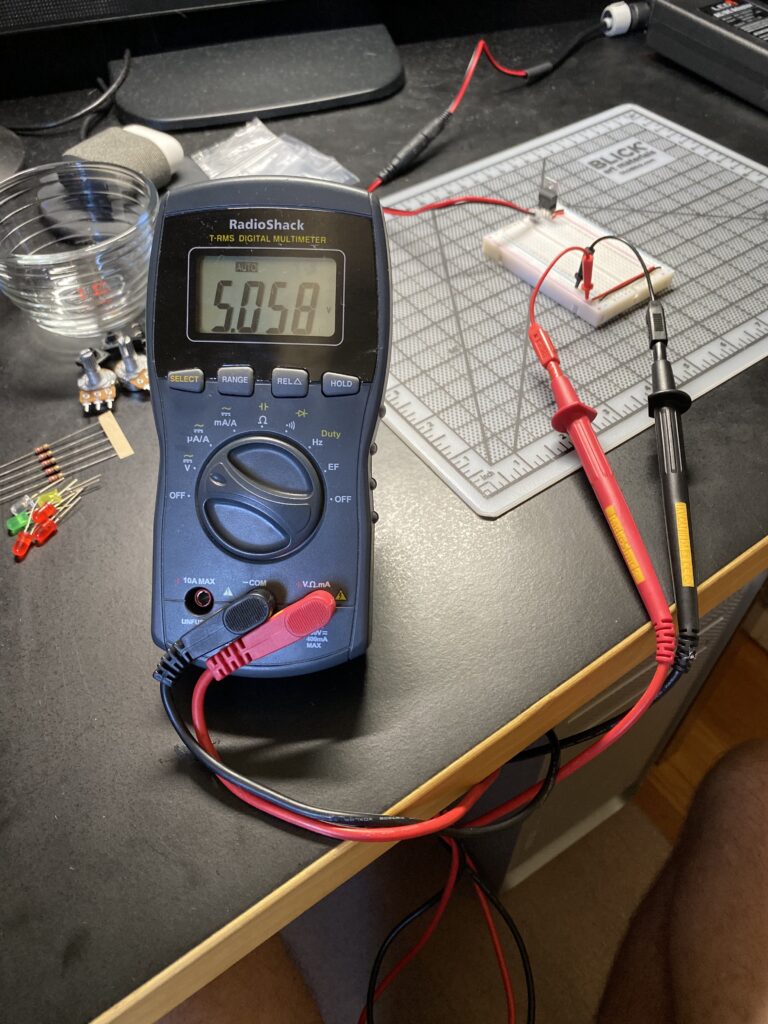
Checking the output from the 7805 voltage regulator my meter read 5.058 volts.
Now lets power up an LED!
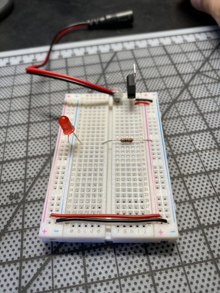
I setup the breadboard with a red LED and 220 ohm resistor. 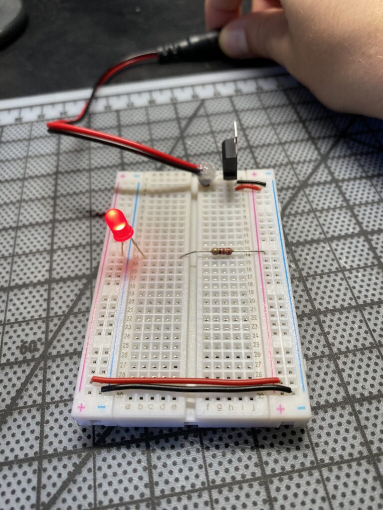
Connecting power to the board a red LED lights up as expected.
Horray! The circuit works!
I learned from this lab that one of my red LEDs was burned out. Thankfully I have back-ups! On to the next lab assignment!


